|
|


 Arabic
 Bengali
 Chinese
 English
 French
 German
 Hebrew
 Hindi
Hindi Italian
 Japanese
 Korean
 Malay
Malay Polish
 Portuguese
 Spanish
 Turkish
 Ukrainian
 Vietnamese
|
ENCYCLOPEDIA OF RADIO ELECTRONICS AND ELECTRICAL ENGINEERING The diagnostic device for the automobile engine with the BOSCH controller. Encyclopedia of radio electronics and electrical engineering
Encyclopedia of radio electronics and electrical engineering / Automobile. Electronic devices Today's high requirements for environmental cleanliness of exhaust and fuel efficiency of cars can only be met when using engines with fuel injection and an electronic control system. The number of cars equipped with such systems is growing in our country. True, on the roads of Russia so far most of them are foreign-made, but there are also many domestic cars. And according to the concept adopted by the Volga Automobile Plant since 2001, all manufactured products will be equipped exclusively with engines with electronically controlled fuel injection. However, it should be noted that with all the advantages of the engines in question, they have a significant drawback in Russian conditions. Even the simplest malfunction cannot be detected and eliminated without contacting a car service, because only there is the expensive diagnostic equipment necessary for this. The device proposed by the author of the article will allow the driver to independently solve many problems associated with the diagnosis of the fuel injection system. In addition, this device duplicates and supplements the readings of the speedometer, tachometer, coolant temperature gauge, voltmeter, econometer. Already today, engines with distributed fuel injection are installed on most front-wheel drive AvtoVAZ vehicles. A specialized controller serves as the central control device for the injection system. Most of the engines are equipped with the Bosch M1.5.4 controller. It processes the information coming from various sensors and acts on the actuators, ensuring optimal engine operation. Having found out the output of any of the parameters beyond the permissible limits, the controller stores the fault code in the internal non-volatile memory and turns on the "Check Engine" display on the car dashboard. Unfortunately, the regular means for various purposes available in the car cannot read the fault code and determine why the display is lit. The M1.5.4 controller issues this code and monitored parameters only to a special connector, to which diagnostic equipment is connected at the service station. There are several types of diagnostic devices. But even one of the simplest - DST-2M - costs about 300 US dollars, which, of course, prevents the widespread use of such devices by motorists. A schematic diagram of a diagnostic tool that you can make yourself is shown in fig. 1. It is based on a single-chip microcomputer AT89S8252-24PC from Atmel (DD2). Every 100 ms, it queries the engine management system for the required parameter and displays its value on the liquid crystal display (LCD) HG1. Two-way communication with the Bosch M1.5.4 controller is organized through the K-Line interface according to the IS09141 specification and the Keyword2000 information exchange protocol. The microcomputer clock frequency (12 MHz) is set by a circuit consisting of a quartz resonator ZQ1 and capacitors C1, C2. The speed of data exchange through the serial port of the microcomputer depends on this frequency, therefore it is unacceptable to use a quartz resonator at a different frequency, communication with the controller will be impossible.
Reliable start of the microcomputer after the supply voltage is applied and blocking its operation in case of its decrease is provided by the KR1171SP42 (DA1) microcircuit. It keeps the output level 3 log. 0 while the supply voltage is less than 4,2 V. Capacitor C3 delays the transition to the log state. 1 after the voltage exceeds the specified threshold. A complete functional and constructive analogue of the KR1171SP42 chip - PST529D from Mitsumi. Given a different pinout, DS1233-15 from Dallas Semiconductor, ADM705 (Analog Devices), MAX705 (Maxim) are also suitable. The latter also contains a watchdog timer designed to send a reset signal when the microcomputer "freezes". If we neglect the possible failures of the device as a result of "dips" in the supply voltage, the DA1 chip can not be installed. The power-on reset signal will form the R1C3 circuit. In this case, it is desirable to increase the capacitance of the capacitor C3 to 1 uF and install any low-power diode in parallel with the resistor R1, for example. KD521A, cathode to +5 V line. Buttons SB0-SB1, used to control the device, and the LCD control circuit are connected to the pins of the P3 port of the microcomputer. Since the port has no internal terminating resistors, the formation of log levels. 1 on its outputs is carried out with the help of external ones, combined into a resistor assembly DR1. Port P2 pins are connected to the LCD data bus. The DV16110S1FBLY/R LCD from Data Vision, indicated on the diagram, is a single-line 16-character LCD with built-in backlight. Instead, another functionally similar one is suitable, provided that its command system is compatible with KS0066, and the character generator is Russified. Suitable, for example, indicators HDM16116H-7 from Hantronic, JA-16101 from JE-AN Electronic, AC 161B from Ampire. The variable resistor R11 serves to adjust the contrast of characters on the LCD screen. The microcomputer turns on and off the LCD backlight using a switch on the VT2 transistor, which can be replaced by any other transistor of the np-l structure with a permissible collector current of at least 817 mA instead of that indicated on the KT150A circuit. The current in the backlight circuit is limited by resistors R8 and R9 connected in parallel. The rated power of each of them is at least 2 watts. The interface unit with the diagnostic circuit (K-Line) of the Bosch M1.5.4 controller is made on transistors VT3 (transmitting key) and VT4 (receiving key), Schmitt triggers DD1.1 and DD1.3. It converts the microcomputer signal, which has TTL levels, to 12-volt according to the IS09141 specification and vice versa. To protect against possible voltage surges, a zener diode VD2 is used. The diagnostic tool is powered from the vehicle's on-board network, which can also experience significant voltage surges. R4 protects against them - a special automotive varistor from S + M (Siemens Matsushita Components) SIOV S10K14AUTO, the resistance of which drops sharply with increasing voltage. It can be replaced by a zener diode with a stabilization voltage of 15 ... 19 V, for example, KS515A or KS518A. Diode VD1 KD248A protects against reverse polarity of the supply voltage. Instead, any other diode with a permissible forward current of at least 300 mA will do. With the help of an integrated stabilizer DA2 KR1157EN501A, a voltage of 5 V is obtained to power microcircuits and LCDs. On the device board, blocking capacitors C6-C8 should be installed in close proximity to the power outputs DA1, DD2 and HG1. The control program of the diagnostic tool consists of modules written in Assembler and C languages for the FSI (Franklin Software Inc) compiler. The program was developed and compiled in the integrated environment PROVIEW32 V3.3.4 Build number 8.63. Assembler - A51 version 6.03.08, C compiler - version 6.11.4C, linker - version 4.08.06. An evaluation version of these tools can be obtained from the FSI website at fsinc.com. The codes of the translated program are shown in the table. Before installing the DD2 chip on the device board, they are written to its FLASH memory using a universal programmer. This option is suitable if a panel is provided on the board for this microcircuit. In such a case, the socket XS1 and the key on the transistor VT1 can be excluded from the device circuit.
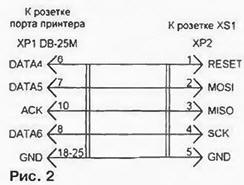
Please note that in devices operated on a car, it is recommended to solder all microcircuit leads directly to the board without adapter panels. In conditions of high vibration, this measure eliminates failures caused by short-term contact failures in the panels. Of course, soldering a programmed chip is risky. But the micro-computer AT89S8252 allows you to enter the program into it even after installation on the board. To do this, the socket XS1 of the device is connected with a cable to the socket of the printer port of a personal computer. The cable diagram is shown in fig. 2, its length is not more than 0,3 m. A special program is launched on the computer, for example, AEC ISP V1.00 from AEC Electronics (aec-electronics.co.nz). Working with it is very simple, you just need to select the desired menu items and follow the prompts that appear on the screen.
Naturally, before programming the microcomputer. the diagnostic tool should be turned on and the serviceability of its main components should be checked. Apply a voltage of 12 V to the contacts of the XP1 plug of the device and. by closing the contacts of the switch SA1, check for the presence of a stabilized voltage of +5 V at the power supply pins of the microcircuits. Then make sure that the reset signal is generated correctly. After turning on the power, a single high-level pulse should be observed at pin 9 of the DD2 microcomputer. Otherwise, the supply voltage control chip DA1 is faulty. At pins 18 and 19 of DD2 there should be a signal with a frequency of 12, and at pin 30 (ALE) - 1 MHz. If there is a signal at terminals 18 and 19, but it is not at terminal 30, then the microcomputer is faulty and must be replaced. If there is no signal at one of the pins 18 or 19, try to match the capacitance of the capacitors C1 and C2 or completely eliminate them. Sometimes a quartz resonator needs to be replaced. Having achieved stable operation of the internal generator, the microcomputer can be programmed. After completing this operation, check that the program memory is correctly addressed. At pin 29 (PME) DD2 there should be a constant high logic level, which means accessing the internal program memory. When pulses are observed here, you should make sure that the log level is present. 1 at pin 31 of the microcomputer. If pulse bursts appear periodically on the PME pin, this means that the address is out of the internal memory. Most likely, the microcomputer is "clean" - the program is not included in it. After the start, the control program initializes the serial port and the system timer of the microcomputer, and then initializes the LCD: it outputs command codes to port P2, accompanied by high logic level pulses at the EZHKI input. Having issued a command, the microcomputer switches port P2 to read mode and waits for a ready signal from the LCD, continuing to give pulses to input E. If the indicator is faulty, there will be no ready signal and the program will "loop" waiting for it. This LCD needs to be replaced. After initialization, the LCD screen will be cleared and the phrase: "Indicator M1.5.4" will appear on it. If only black squares are visible, it is necessary to adjust the image contrast with a variable resistor R11. Simultaneously with the output of the splash screen, the microcomputer sets a low logic level at pin 35 (P0.4) - the indicator backlight turns on. After a pause of 3 s. the program is trying to establish a connection with the Bosch Ml.5.4 controller. At pin 11 of the microcomputer, every 300 ms a low-level pulse with a duration of 30 ms appears, after 150 ms after it several bytes of data are transmitted at a speed of 10400 bps. A similar signal with an amplitude of 12 V should be on pin 1 of the XS2 socket (K-Line circuit), otherwise check the key on the VT3 transistor. If everything is OK and the LCD shows "No Communication", the scan tool test is complete and is ready to be connected to the fuel injection system control unit. With a relatively rare use of the device, it can be powered from the cigarette lighter socket in the car. However, turn on the device only after turning on the ignition. The fact is that the Bosch M1.5.4 controller always starts its work by trying to establish communication with the immobilizer by sending appropriate commands to the K-Line circuit. If a diagnostic tool is already connected to the diagnostic line and is transmitting, a conflict occurs and the engine may stall. This is a rare but possible situation. It is to exclude it that the diagnostic tool waits 3 seconds before the first attempt to contact the controller. When installing the device for permanent operation, it is recommended to apply +12 V voltage to it from terminal 87 of the main relay of the injection system. This will make it impossible to turn on the device when the ignition is off. The contacts of the XS2 socket are connected to the diagnostic block, as shown in fig. 3.
On vehicles not equipped with an immobilizer, the connection of the information line (K-Line) of the Bosch M1.5.4 controller with the M contact of the diagnostic block is usually broken. To install it, you need a jumper between terminals 9 and 18 of the block for connecting the immobilizer. If the car has previously been diagnosed in a car service, such a jumper probably already exists. There are two modes of operation of the diagnostic tool: displaying the value of a user-selected parameter or fault codes with the possibility of erasing them from the controller's memory. After switching on, the mode of displaying the current value of the parameter that was selected before switching off the device will be automatically set:
The parameter is selected using the arrow buttons (SB1, SB2). To switch to the display of fault codes, press and release the "Mode" button (SB3). The LCD will display the number of codes stored in the controller's memory. If it is equal to zero, the next time you press the "Mode" button, the device will return to the display of parameters. If there are fault codes, they can be viewed using the arrow buttons. To exit the code display mode without erasing them, briefly press and release the "Mode" button. To erase the codes from the controller memory, keep the button pressed for more than 2 seconds. After erasing, the LCD should display the number "zero" - a sign that there are no codes left in the controller's memory. In the event of a break in communication with the Bosch M1.5.4 controller, the message "No connection" will appear on the LCD of the diagnostic tool. After its resumption, the mode that was in effect before is automatically restored. Author: A. Alekhin, Khimki, Moscow Region
Artificial leather for touch emulation
15.04.2024 Petgugu Global cat litter
15.04.2024 The attractiveness of caring men
14.04.2024
▪ Fighting heat with cold roofs ▪ Microplastics found in plant leaves ▪ Innovative TDK-Lambda DRF Power Supplies ▪ VL6180X - distance, light and gesture sensor
▪ section of the site Big encyclopedia for children and adults. Selection of articles ▪ article Ride a hare. Popular expression ▪ article What is philosophy? Detailed answer ▪ article Elusive ring. Focus Secret
Home page | Library | Articles | Website map | Site Reviews
www.diagram.com.ua |


 Leave your comment on this article: