|
|


 Arabic
 Bengali
 Chinese
 English
 French
 German
 Hebrew
 Hindi
Hindi Italian
 Japanese
 Korean
 Malay
Malay Polish
 Portuguese
 Spanish
 Turkish
 Ukrainian
 Vietnamese
|
ENCYCLOPEDIA OF RADIO ELECTRONICS AND ELECTRICAL ENGINEERING Semi-automatic octane corrector. Encyclopedia of radio electronics and electrical engineering
Encyclopedia of radio electronics and electrical engineering / Automobile. Ignition Owners of veteran cars during operation face a number of specific problems - this is an excessive percentage of CO in the exhaust gases, and low throttle response of the car, and difficult engine start, etc. Consideration of options for solving these problems leads to the conclusion that, in addition to engine overhaul or buying a new car, there are more acceptable ways: for example, installing an electronic ignition unit and an octane corrector. Experiments with electronic ignition units, the descriptions of which were published in the Radio magazine, showed that on an old car the unit proposed by V. Bespalov is the most effective (Electronic Ignition Unit. - Radio, 1987, No. 1, pp. 25-27 ). As for the octane corrector, none of the known ones satisfied me. Therefore, I decided to develop my own design, taking into account all the interesting things invented by other authors. It is known that the best performance of a gasoline internal combustion engine can only be realized when the current ignition timing (OZ) depends on the crankshaft speed, on the vacuum in the carburetor, on the humidity of the ambient air, on the octane number of the fuel used and much more. On modern expensive car models, very complex and expensive on-board processors are installed for this purpose, which summarize the readings of a large number of sensors that take these factors into account. The creation of such complexes for radio amateurs is difficult. Your old car is equipped only with a centrifugal OZ angle regulator and a vacuum corrector. Fuel, as you know, is now traded by several companies, and its quality, even with the same brand, can be very different. Therefore, experts consider it expedient to manually adjust the angle of the OZ after the next refueling. The corrector described below makes it possible to automatically delay the moment of sparking by 2,5 ms when starting the engine, and with an increase in the crankshaft speed from 960 min-1 to 4000 min-1, the delay decreases linearly (at 4000 min-1, the delay is close to zero). From the driver's cab, you can quickly change the delay in the range from 0 to 2,5 ms, which at idle corresponds to an OZ angle of 14,4 degrees. The corrector can work in conjunction with any electronic ignition units. It is connected at the input in parallel with the contacts of the breaker (see the diagram in Fig. 1). The principle of operation is to bypass the interrupter for a delay set by the driver.
The device is powered by a parametric stabilizer R1VD1. When the contacts of the breaker open, the opening voltage is supplied to the base of the closed transistor VT1 through the resistor R2. As soon as the transistor VT1 opens, the high level at the inputs of the element DD1.1 is replaced by a low level, and at the output of this element, on the contrary, a high level appears. At this moment, one-vibrators are launched, one assembled on the DD2.1 trigger, and the second on the DD2.2 trigger. At the same time, a high level, passing through the resistor R3, confirms the open state of the transistor VT1. The first of the single vibrators generates pulses of constant duration. From the inverse output of the trigger, the pulses, after being inverted by the DD1.2 element, are fed to the input of the frequency-voltage converter assembled on the elements VD5, R10, R11, C5, and from the direct output to another similar converter on the elements VD4, R8, R9, C6. The VD5R10R11C5 converter is used to control the crankshaft speed at the starting section to idle (i.e., at a sparking frequency from 0 to 27 Hz). The principle of operation of the converter is to charge the capacitor of the integrating circuit with pulses of constant duration, which ensures a linear dependence of the voltage across the capacitor on the frequency of the input pulses. The second single vibrator with adjustable duration of the output pulses generates a delay of the sparking pulse relative to the moment of opening the breaker contacts. Up to this point, the trigger DD2.2 is in state 0, the output of the element DD1.3 is low, so the transistors VT2 and VT3 are closed. After opening the contacts, the trigger DD2.2 will switch to state 1, at this moment the transistors VT2, VT3 will open, again lowering the voltage at the base of the transistor VT1 almost to zero. The transistor will close, and the output of the element DD1.1 will again appear low, but it will not change the state of the triggers. The single vibrator generates a delay pulse, the duration of which is determined by the resistance of the circuit of resistors R13, R14 and the capacitance of the capacitor C4 (if the transistor VT4 is closed). That short increase in voltage at the input of the ignition unit, which occurs between the moments of contact opening and opening of transistors VT2, VT3, does not lead to a spark - it will be suppressed by the "anti-bounce" input circuit of the ignition unit. When the sparking frequency is less than 27 Hz, the output of the element DD1.4 is high, the transistor VT4 is open, so the capacitor C3 is connected in parallel with C4. As a result, the duration of the delay pulses increases by 0,5...1,5 ms, which makes it easier to start the engine. At a frequency of more than 27 Hz (idle engine speed and above) at the output of the DD1.4 element, the level changes from high to low, the transistor VT4 closes and the capacitor C3 is disconnected from C4 at the same time, the delay is reduced to the value set by the resistor R13. The trigger returns to state 0 when the voltage across capacitor C4 increases to 4,6 V, after which the capacitor is discharged through resistors R13, R14. The duration of the delay pulse generated by a single vibrator on the DD2.2 trigger depends on the initial voltage on the capacitor C4, and it is determined by the frequency-voltage converter on the elements VD4, R8, R9, C6 and the emitter follower on the transistor VT5; they prevent the capacitor from discharging below a certain level. The higher the crankshaft speed, the higher the voltage at the emitter of the transistor VT5 and the less time it takes to charge the capacitor C4 to the trigger switching voltage, and hence the shorter the delay. At a sparking frequency of 133 Hz (4000 min-1), the voltage at the emitter of the transistor VT5 is 4,6 V and the single vibrator on the DD2.2 trigger does not start, the delay is zero. With decreasing frequency, the voltage at the VT5 emitter decreases and the delay is restored. Otherwise, the octane corrector is similar to others, those that are already known to the readers of the magazine. All parts, except for the variable resistor R13, are mounted on a printed circuit board (Fig. 2) made of foil fiberglass 1,5 mm thick, which is mounted in a box glued from sheet polystyrene. Capacitors - K50-38 (C1), the rest - K10-7a or K10-17; resistors - MLT. Zener diode D814B can be replaced with D814V. Diode VD2 - any of the KD243 or KD105 series, the rest - any of the KD521, KD522, D220 series. Transistors KT315G (VT1, VT4, VT5) are replaceable by any of the KT315 series, as well as KT3102, taking into account the pinout; KT503G and KT817G - any of the corresponding series.
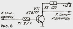
Resistor R13 is installed in a convenient place on the dashboard of the car. The resistor knob should be equipped with at least the simplest scale with a pointer. To establish a corrector, you will need an electronic oscilloscope with a standby sweep mode, an electronic frequency counter, a power supply for a constant voltage regulated within 11 ... 14 V, and a current of at least 1 A, a chopper simulator, and a low-frequency rectangular pulse generator. First, the corrector is connected to the power supply and the voltage on the zener diode VD1 (about 9 V) is measured with a voltmeter, which should not change by more than 0,3 V when the input voltage changes within 11 ... 14 V. Then a simple simulator is connected to the generator output breaker, assembled according to the scheme in Fig. 3, set the pulse repetition rate on the generator to 25 Hz and control the rectangular pulses with an amplitude of about 12 V at the output of the simulator with an oscilloscope. Connect the output of the chopper simulator to the input of the octane corrector and control the passage of control pulses at the collector of the transistor VT1 and at the output of the element DD1.1 with an oscilloscope.
By selecting the resistor R7, they achieve a pulse duration of 3,5 ms on the oscilloscope at the direct output of the trigger DD2.1. The oscilloscope input is switched to the output of the DD1.4 element, and by changing the generator frequency from 20 to 30 Hz, the resistor R11 is selected so that the DD1.4 inverter clearly switches from a single state to zero when passing through a frequency of 27 Hz. Next, set the input signal frequency to 133 Hz and select the resistor R9 until a voltage of 4,6 V is obtained at the emitter of the transistor VT5. Using an oscilloscope connected to the direct output of the DD2.2 trigger, make sure that there is no delay when the input signal frequency increases above 133 Hz. When the frequency of the input signal changes from 33 to 133 Hz, the voltage at the emitter of the transistor VT5 should change linearly from 0 to 4,6 V. This will ensure a linear decrease in the delay from the value determined by resistor R13 to zero. At the maximum resistance of the resistor R13, the greatest delay is set to 2,4 ... 2,5 ms at an input frequency of 33 Hz by selecting the capacitor C4 and 3,4 ... 3,6 ms at an input frequency of less than 27 Hz by selecting the capacitor C3. In conclusion, using an oscilloscope, the pulse sequence at the input of the corrector is monitored. The lower voltage level must be within 0,5 ... 0,7 V, and the upper - 11 ... 14 V. The added duration of the lower level may be different - if the input signal frequency is less than 27 Hz and the resistance of the resistor R13 is maximum, it equal to 3,5 ms; at a frequency of about 33 Hz with resistor R13, it can be changed from 2,5 ms to 0, and at 133 Hz or more there is no delay. If the corrector provides the specified parameters, the adjustment can be considered complete. Install the corrector in the cabin. The corrector is connected to the electrical system, its handle is set to the middle position and the engine is started. After the next refueling, the position of the corrector knob is clarified. To do this, on a flat section of the highway, the car is accelerated in direct gear to a speed of about 60 km / h. Press the accelerator sharply and evaluate the time during which the characteristic ringing of the piston fingers is heard. The duration of the ringing for more than 3 s indicates an insufficient delay, which requires reducing the ignition timing with the corrector knob. If there is no ringing, the delay is reduced. The optimal ringing duration is 0,5 ... 1 s. You can use the octane corrector in a slightly different way. In this case, the operation of the centrifugal regulator in the breaker-distributor is blocked (either the crackers are tied with wire, or they are dismantled), and the breaker-distributor housing is turned towards the ignition advance by an angle corresponding to the angle of OZ 35 degrees. relative to the top dead center of the piston of the first cylinder. In this position, the change in the OZ angle will correspond to the factory setting of the centrifugal regulator, i.e., its role will be played by the octane corrector. Author: A.Sergeev, Kamensk-Shakhtinsky, Rostov region.
Air trap for insects
01.05.2024 The threat of space debris to the Earth's magnetic field
01.05.2024 Solidification of bulk substances
30.04.2024
▪ Simple technology for the production of speakers in rolls ▪ Raised mice with human cells ▪ Fibocom LTE Cat 1 IoT Module ▪ External graphics cards for Thunderbolt 3 laptops
▪ section of the website Experiments in Physics. Selection of articles ▪ macroeconomics article. Crib ▪ article What is a rheumatic attack? Detailed answer ▪ article mast lift driver. Standard instruction on labor protection ▪ article Sound relay. Encyclopedia of radio electronics and electrical engineering
Home page | Library | Articles | Website map | Site Reviews
www.diagram.com.ua |


 Leave your comment on this article: