|
|


 Arabic
 Bengali
 Chinese
 English
 French
 German
 Hebrew
 Hindi
Hindi Italian
 Japanese
 Korean
 Malay
Malay Polish
 Portuguese
 Spanish
 Turkish
 Ukrainian
 Vietnamese
|
ENCYCLOPEDIA OF RADIO ELECTRONICS AND ELECTRICAL ENGINEERING Four-channel home theater amplifier with LG player remote control. Encyclopedia of radio electronics and electrical engineering
Encyclopedia of radio electronics and electrical engineering / Transistor power amplifiers The amplifier is made on microcircuits, therefore it does not require adjustment, it is easy to use and has rather high technical characteristics. When developing and manufacturing the device, the author proceeded from the following considerations. When operating a home theater (DC), it is desirable to control it from the remote control, and there are quite a lot of them in everyday life.
In this design, control is carried out from the remote control of the DVD player, using the TV control buttons (see photo in Fig. 1). From the "good old days" many have left various speakers and dynamic heads, which are both a pity to throw away and have nowhere to use. Popular at the time AC 35AC-01 or their modifications can be successfully used as front ones. In this case, the subwoofer becomes unnecessary, and the speakers of the TV can be successfully used as a center speaker, especially since all modern TVs have a remote control. It is worth noting that the quality of discs on the market leaves much to be desired. I came across 5.1 format discs (especially with translation into Russian), when playing which the sound of the center channel had to be turned off altogether. By excluding the center channel and subwoofer (in the DVD playback settings), the sound information is distributed among the front channels. It is known that due to the structural features of the human auditory apparatus, the localization of sound images in the stereo panorama occurs in the mid-frequency range. Therefore, almost any broadband dynamic heads in acoustic design can be used as rear ones. It has been noticed that although both sound sources (TV tuner and DVD player) are digital with analog outputs, their timbre is still different, so it was decided to make the timbre settings independent for each sound source. In 5.1 format, the nominal sound levels in the front and rear channels should be approximately the same. In the 2.0 format, the rear channels are used as "backlight", so the level in these channels must be lowered. Balance adjustments should also be independent of the mode of operation. In many areas, especially in the outback, the quality of the power grid still leaves much to be desired. Sudden shutdown and even more sudden switching on of light, phase imbalance, ceiling leaks, etc. incidents suggest that it is not advisable to leave electrical appliances constantly plugged into the network. Although many are already accustomed to the fact that such devices are constantly ready for use, that is, they are in standby mode. Therefore, it was decided, in addition to the standby mode, to be able to completely disconnect the recreation center from the network. And especially for the forgetful, a switchable power timer has been introduced. In addition, when the device is in standby mode for more than 5 minutes with the timer turned off, a notification is periodically displayed on the display screen that the timer is turned off and, therefore, the device must be turned off forcibly. The management of the DC should be as simple as possible, and the display indication should be informative and intuitive. Therefore, it was decided to quickly manage the switching of the operating and standby modes, adjust the overall volume, select the sound source and its mode. Other adjustments can be called through the menu. Parts must be available and cheap; finally, a home-made design is always your own choice and preferences, which is worth a lot for a radio amateur. All this is implemented in the proposed design. Device layout The schematic diagram of the device is shown in fig. 2. The inclusion of all microcircuits and modules is typical, recommended by manufacturers. The microcircuit of the four-channel UMZCH TDA7384 with a maximum short-term power of 4x25 W at a load of 4 ohms (with a supply voltage of 14 V) is popular not only among motorists [1].
The input circuits are organized so that it is possible to select the sound source and its mode using the AV button through the D2-D4-S2-D2 ring, etc. The D4 mode is used when watching DVD movies with 5.1 sound. D2 mode is used when watching DVD movies with 2.0 audio and listening to audio CDs; in this case, the stereo mode with "backlight" is realized. S2 mode is used when receiving channels from a satellite receiver or any other stereo source. The DC uses two TDA7313 sound processor chips (DA1, DA2) with the same addresses. In order to realize the advantages of a two-wire bus, save microcontroller port outputs and provide the ability to adjust the front and depth balance, the signals to the power amplifier are fed from different outputs of the TDA7313 microcircuits: to the front channels - from the main outputs of one microcircuit (DA1), and to the rear channels - from additional outputs another (DA2). As can be seen from the diagram, the liquid crystal display (LCD) module is powered by the output current of the microcontroller port. The typical current consumption of the applied module is about 1 mA, and the load capacity of the outputs of the microcontroller ports is limited to 20 mA. This solution allows you to programmatically enable and disable the module and removes all problems with initialization. The key on VT1 controls the backlight LED of the LCD module. Backlight current - no more than 50 mA; it is set by selecting the resistor R1. Conclusion 3 HG1 is designed to adjust the contrast of the indicator, in my copy it turned out to be enough to connect it to a common wire. The RB1 output of the microcontroller is used for automatic power management. Immediately after initialization, the microcontroller sets it to a high level. When the timer expires or the power is forcibly turned off, the level becomes low. This signal can be used to control an electromechanical or electronic power-on relay. A quasi-resonant voltage converter, described in [2], with some modifications, was used as a power source. About details There are no special requirements for the details of the "strapping" of microcircuits, however, it is not recommended to use ceramic capacitors with non-rated TKE of groups H50-H90 in the signal circuits of processors and amplifiers. Oxide capacitors need to be checked for capacitance, leakage and allowable ESR values. Stabilizers can be replaced by any low-power ones, including those based on discrete elements. Photodetector unit - any type; it is only important that its resonant frequency coincides with the carrier frequency of the remote control signals. The device uses a single-line LCD module with a familiarity size of 9,7x4,84 mm - BC1601DGPLCH. The use of a single-line module is dictated by the desire to minimize the height of the device case. This module is based on the KS0066 controller and has the following feature. One 16-character string actually consists of two, 8 characters each. This somewhat complicates the program control of the module, but reduces its cost. As HL1, a small-sized super-bright LED (for example, blue NVZV-448ABSA) with an initial glow current of less than 1 mA was used. About the program The PIC16F84 was chosen as the controller, as one of the most common, simple and mastered by many fans. The program was developed and debugged in the Proteus_6.7sp3 system, it does not use the watchdog timer and takes up about 80% of the program memory (there is room for improvement). The controller configuration and data for the EEPROM are in the program text. It should be noted that in the Proteus_6.7sp3 simulator there is a model of a single-line LCD module called LM020L, but it has several differences from BC1601. Firstly, it has a single 16-character string, secondly, the screen shift control bit is inverted, and thirdly, the code table does not match. You can minimize the differences as follows: in the editing window of the LM020L component, replace the line {ROW1=80-8F} with the line {ROW1=80-87 С0-С7}; replace the LCDALPHA.DLL file in the MODELS folder of the Proteus 6 Professional program with the TOPICMODELLCDALPHA.DLL file from the folder in additional materials. In the same place, in additional materials, in the TOPICMODEL folder, there is the source code of the program (unch.asm), the corresponding HEX file (UNCH.HEX) and the device model for the Proteus system (unch.DSN). The model can be run by clicking on the execution and see it in action. The power is turned on by briefly pressing the PSU "POWER" button (not shown in the diagram) on the front panel of the device. In this case, the HL1 LED lights up, and the device is switched to standby mode. The POWER button switches the DC to standby (ST-BY) mode. Pressing this button again, if the device is in standby mode, turns off the DC power either by a timer or immediately (if the timer is off). The last minute of the timer operation is indicated on the display with a countdown. The transition of the recreation center from standby mode to working mode is carried out using any remote control button (of course, in the control zone) at any time while the HL1 LED is on, which indicates the standby mode (ST-BY). The AV button switches the inputs and the input mode in a ring (see above). At the same time, with each switch, the volume gradually increases to the previously set level and the corresponding balance and tone settings are loaded. Use the PR- / PR+ buttons to scroll through the menu items in the forward and reverse directions. If the sign S2 or D2/4 appears on the left side of the display, this means that the setting is individual for the selected mode. The VOL- / VOL+ buttons change the value of the regulation parameter, the name of which is displayed on the display at the moment. If the parameter has a digital value, then it is displayed on the right side of the display, in decibels for levels (in steps provided for TDA7313) and in seconds for time parameters. Insignificant digits are extinguished. The position of the tone controls is displayed with a sign, and the balance is displayed as a difference in conditional levels (for example, the front level is 5 dB more than the rear level). The direction of adjustment is assigned as follows. The VOL + button shifts the sound localization point to the right or towards the front, and the VOL- button, respectively, to the left or towards the rear. If the device is in operating mode and no commands are given from the remote control, then after a period of time determined by the WIPE parameter, all the parameters available for change will be displayed cyclically (a kind of splash screen). In the "screen saver" mode, when the VOL- or VOL + command is given, the program will switch to volume control, by the PR- or PR + commands - to the previous or next function from "VOLUME", respectively. The BASS menu item can be set to ON or OFF. This turns on / off the frequency response correction in the low-frequency region (thin-pension). The timer also has two states: either ON (approximately 5 minutes) or OFF. The WIPE parameter determines the period for changing information on the display in the screensaver mode and the time for the notification of the off timer to be displayed, see above. It can be changed from Off to 60 seconds in 5 second steps. Parameters are written to the non-volatile memory automatically when the power is turned off, and read into the RAM after the power is turned on. In order to save the resource of the microcontroller, only those parameters that have changed in the current session are updated in the non-volatile memory. All text messages, with the exception of some characters that are generated by software, are located in EEPROM. The program uses the address of the text and the number of characters in it, this must be taken into account when replacing the inscription. The I2C protocol provides for a special confirmation signal (ACK) that the receiver (TDA7313) generates when information is successfully received from the transmitter (microcontroller). In this design, the ACK signal is generated by software. This decision is due to the following considerations. The I2C control bus is quite versatile and is designed to work with a different number of master and slave devices, which can have different clock frequencies, speed, manufacturing technologies, supply voltage, and then the issues of noise immunity and reliability are of fundamental importance. The confirmation signal serves as one of the elements to ensure these requirements. But in our case, we have exclusive control of the master device by almost one slave, and the transmitter and receiver are located on the same board at a minimum distance from each other. Therefore, noise immunity is provided here constructively. The I2C digital bus is described in detail in [3]. About remote control This design was developed for the LG DF599X DVD player with a built-in multi-channel audio decoder. If the model of the DVD player matches the author's, then you need to take into account that nine types of encodings are provided by the player's manufacturer to control TVs from different manufacturers. In the author's version, encoding No. 9 is used (it is also wired into the Proteus system model). The choice of this particular encoding is due to the fact that the structure of its commands is fundamentally different from the vast majority of others.
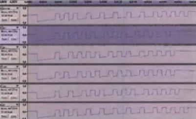
On fig. 3 shows oscillograms of commands for all buttons used in the design of the remote control. A visual analysis of the structure of these signals was possible using the Audacity sound editing program. From fig. 3 shows that the commands are quite short - only 12 information pulses, of which only 8 are, in fact, the button code. The pulse durations are related as 4:2:1. Thus, the shortest pulse is interpreted as 0, twice as long as 1, and quadruple as start. The last four pulses can be used for noise immunity and stop identification (high). In the absence of a carrier, a high level is always active at the output of the photodetector, so low will be active. Noise immunity is provided by sending the command three times. When you hold the button, the commands themselves are generated, and not a special code combination, as in other encodings. The numerical values of the button codes, with the exception of one, form a sequential series, which makes it very easy to organize a calculated transition in the program. Thus, the decoding of commands is extremely simple and reliable, during the operation (more than a year) there was not a single failure. Of course, you can use other remote controls with a different encoding. To do this, you need to study the structure of commands, measure the timing parameters and decide on their interpretation. An archive with additional materials is available at ftp://ftp.radio.ru/pub/2009/11/domkino.zip. Literature
Author: G. Vorontsov
Machine for thinning flowers in gardens
02.05.2024 Advanced Infrared Microscope
02.05.2024 Air trap for insects
01.05.2024
▪ Fujitsu ETERNUS CD10000 56 petabyte storage ▪ Gardening is one of the best antidepressants ▪ Philips GoPix 1 Pocket Portable Projector ▪ Epson PowerLite Home Cinema 2 3D/2030D projector ▪ Happiness hormone can cause depression
▪ site section Parameters of radio components. Article selection ▪ article by Michael Cunningham. Famous aphorisms ▪ article Are locusts dangerous? Detailed answer ▪ article Fiberization plant operator. Job description ▪ article A bit about circuit boards. Encyclopedia of radio electronics and electrical engineering
Home page | Library | Articles | Website map | Site Reviews
www.diagram.com.ua |


 Leave your comment on this article: