|
|


 Arabic
 Bengali
 Chinese
 English
 French
 German
 Hebrew
 Hindi
Hindi Italian
 Japanese
 Korean
 Malay
Malay Polish
 Portuguese
 Spanish
 Turkish
 Ukrainian
 Vietnamese
|
ENCYCLOPEDIA OF RADIO ELECTRONICS AND ELECTRICAL ENGINEERING Dual-band VHF FM radio receiver on the K174XA34A chip. Encyclopedia of radio electronics and electrical engineering
Encyclopedia of radio electronics and electrical engineering / radio reception The basis of the device is a specialized microcircuit of the VHF FM radio receiver K174XA34A, it is equipped with an LED tuning indicator and an UHF on the TDA2003 microcircuit. Main Specifications
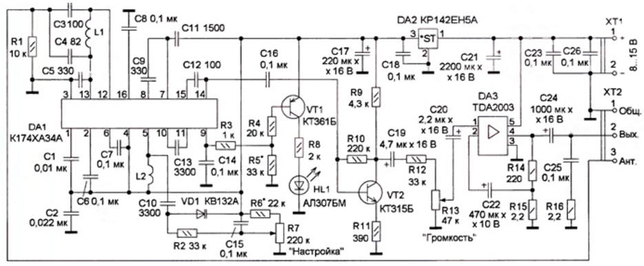
The radio receiver circuit is shown in fig. 1 The signal received by the antenna, through pin 3 of the XT2 block, is fed to the input circuit L1C3C4 and then to the input of the RF receiver DA1. The inclusion of the microcircuit is standard and is described in detail in [1]. They are tuned to the radio station by changing the resonant frequency of the oscillatory circuit of the local oscillator, consisting of an inductor L2, a capacitor C10 and a varicap VD1. A constant voltage is supplied from the variable resistor R7 to the varicap VD1, changing its capacitance, and hence the frequency of the local oscillator of the receiver DA1. The applied KV132A varicap provides coverage of two VHF FM broadcasting bands - 65,8 ... 74 and 87,5 ... 108 MHz and allows you to receive sound accompaniment of television channels located between these ranges. On the transistor VT1 and the LED HL1, an indicator for tuning to a radio station is assembled. At pin 9 of the DA1 chip, a constant voltage is generated, inversely proportional to the level of the received signal. With fine tuning to the radio station, the voltage at pin 9 of DD1 decreases, the transistor VT1 opens and the HL1 LED turns on. The sensitivity of the indicator is set by selecting the resistor R5. The output signal 34 through the capacitor C16 is fed to the input of the pre-amplifier on the transistor VT2, and after amplification - to the volume control R13. Power amplifier 34 is assembled on a DA3 chip without the use of a heat sink, and its output power should not exceed 1,5 watts. To obtain more power, the specified microcircuit should be installed on a heat sink. The receiver chip DA1 is powered by an integrated voltage regulator DA2. All elements, except for variable resistors, are mounted on a printed circuit board made of one-sided foil fiberglass, the drawing of which is shown in Fig. 2. Fixed resistors - MYAT, S2-23, variable resistor R7 - SPZ-23A, SPO, SP4-1 with a resistance of 100 ... 220 kOhm, R13 - SPO, SP4-1 or SPZ-4V with a power switch. Oxide capacitors - K50-35 or imported, the rest - K10-17.
The K174XA34A chip can be replaced with its upgraded version of the KR174XA34R or the foreign analogue TDA7021, and the TDA2003 chip with the domestic K174UN14 chip. Analogues of the integrated stabilizer KR142EN5A-7805, VC7805CT The KT361B transistor can be replaced by any of the KT203, KT209, KT361 series, and KT315B - by any of the KT312, KT315, KT342 series, the LED is of red glow with a rated current of up to 20 mA, All coils are frameless, L2 is wound with PEV-2 0,8 wire , on a mandrel with a diameter of 6 mm and contains 7 turns, and L1 - wire PEV-2 0,5 on a mandrel with a diameter of 5 mm and contains 5 turns. Dynamic head BA1 - any power up to 10 W and a voice coil resistance of 4 ... 8 ohms, for example 4GDSH-4. The receiver chip is installed in the panel. Terminal blocks - 308 series with 2,54 mm pitch When using the radio in adverse reception conditions (low ground, a great distance from the radio station), as well as to increase the sensitivity, you can use a resonant radio frequency amplifier that is connected between the antenna and the input of the radio [2] Before setting up the receiver, an antenna is connected to pin 3 of the XT2 block - a piece of wire 1 ... 1,5 m long, and a dynamic head is connected to pins 1 and 2 and power is supplied. Tuning into radio stations, determine the tuning range. Comparing it with an exemplary radio receiver, they correct the boundaries of this range by stretching or compressing the turns of the L2 coil. The width of the range can be changed by selecting the resistor R6; when the resistance decreases, the range expands. By selecting the resistor R5, it is necessary to achieve a clear turn on of the HL1 LED when fine tuning to the radio station and turn it off when tuning out . The maximum sensitivity is set by first tuning to a radio station near a frequency of 88 MHz. To do this, by reducing the length of the antenna, stretching or compressing the turns of the L1 coil, the best reception quality is achieved. After the adjustment is completed, the coils are fixed on the board with paraffin. Literature
Author: A. Lesovoy
Artificial leather for touch emulation
15.04.2024 Petgugu Global cat litter
15.04.2024 The attractiveness of caring men
14.04.2024
▪ STM32G031Y8Y - 64 MHz controller with SMD component dimensions ▪ The driver will always notice the pedestrian ▪ Fast trains are not the best ▪ Program for the construction of synthetic DNA ▪ Electronic Willpower Trainer
▪ section of the site Microcontrollers. Article selection ▪ article Steering wheels on threads. Tips for a modeler ▪ How did national anthems originate? Detailed answer ▪ article Thyme. Legends, cultivation, methods of application ▪ article Colored hats. Focus Secret
Home page | Library | Articles | Website map | Site Reviews
www.diagram.com.ua |


 Leave your comment on this article: