|
|
ENCYCLOPEDIA OF RADIO ELECTRONICS AND ELECTRICAL ENGINEERING Vertical directional antenna. Encyclopedia of radio electronics and electrical engineering
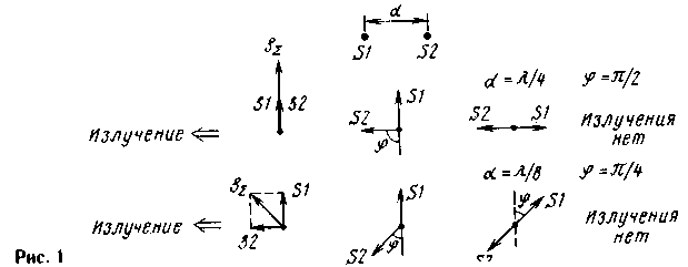
Encyclopedia of radio electronics and electrical engineering / HF antennas The task of creating a directional antenna with vertical polarization is not as simple as it seems at first glance. It would seem that he turned the elements of a conventional beam (wave channel) vertically, and everything is in order, but the question arises of attaching such an antenna to the mast. On VHF, you can move the carrier beam to the side of the mast, in the direction of radiation, but such an antenna turns out to be mechanically unbalanced and requires a very thick and strong mast for its attachment. The main advantages of vertical antennas disappear - small horizontal dimensions, lightness and ease of installation. But more on this later, but first we need to dwell on the chosen concept of a vertical directional antenna. The desire to design a simple and lightweight antenna made us turn to the design of the ZL-beam, which contains only two active-powered elements and has very small dimensions in length of the order of L / 8 ... L / 10. At the same time, the directivity factor (DFA) of this antenna is quite significant and equivalent, as indicated in the literature, to the DFA of a three-element beam with passive elements. The same idea is used in the "Swiss square", which also has very good parameters and even higher directivity. Therefore, the principle of operation of these antennas deserves careful analysis, which we will now do. Let us take two hypothetical point radiators S1 and S2, located at a distance d, as shown in Fig. 1 on top. Let the transmitter power be divided equally between the emitters, so the amplitudes of the fields created by the emitters will be the same. But the excitation phases of the emitters must be different in order to obtain directional radiation. To begin with, let us consider the simplest case, when d = V4, and the radiators are fed in quadrature, i.e. the phase shift of the oscillations applied to them is 90°. On the vector diagram (in the middle row, in the middle), the oscillations of the emitters are shown by the vectors s1 and s2. The angle φ corresponds to an additional phase shift of oscillations up to 180°. We also agree that the phase incursion (phase lag) when a wave propagates over a certain distance is taken into account by rotating the vector clockwise by the appropriate angle. So, for example, a wave that has traveled a quarter-wave path will acquire a phase incursion of 90°. Let us consider the radiation of the system to the right, and the phases of the waves will be measured directly near the emitter S2 (with further propagation to the right, both waves from two emitters will acquire the same phase incursion, and the phase relation between their oscillations will not change). The corresponding vector diagram is shown in the middle row on the right. The oscillation s2 will not change, and the oscillation s1 will acquire a phase shift of 90° after passing the path L/4. As a result, the waves will be out of phase and there will be no radiation in this direction. When waves propagate to the left side of the emitters, the vector s1 will remain in the same position, and the vector s2 will rotate 90 ° clockwise, since the wave from the emitter s2 will pass the path L / 4. The vector diagram of oscillations near the emitter s1 is shown in Fig. 1 in the middle row on the left. It can be seen that the waves from the emitters S1 and S2 are added in phase and the total oscillation acquires a doubled amplitude. In exactly the same way, one can find the radiation field in other directions. For a more figurative representation, we can assume that Fig. 1 shows a plan view of two whip antennas S1 and S2 from above. Such a system of two pins will have a radiation pattern close to a cardioid. The radiation maximum will be directed to the left, and the radiation zero will be directed to the right. In the lateral directions (up and down in the figure), the system will also radiate, and quite significantly, since two quadrature waves will add up in these directions. It is possible to slightly increase the sharpness of the radiation pattern by placing the emitters S1 and S2 closer to each other, for example, at a distance of L/8. Vector diagrams for this case are shown in the bottom row in fig. one. Based on the fact that radiation to the right, as before, should be absent, we determine the phase shift of the oscillations of the emitters. It should be 4p/135 or 1° as shown in the vector diagram in the center of the bottom row. Then, when emitted to the right, the oscillation vector s4 will turn by an angle of n / 45 or 2 °, and will be in antiphase with the vector s1 (see the vector diagram in the lower row on the right). When emitting to the left, the vectors s2 and s1,41 will no longer be in phase, but will be in quadrature, and the resulting field amplitude will no longer double, as in the previous case, but will be only 2 times greater than the field of each of the emitters (vector diagram on the left ). The radiation to the side will also be less, since fields close to antiphase are added in these directions. The distance between the emitters can be made even smaller, but to obtain unidirectional radiation, the angle , which complements the phase shift in the emitters to antiphase, must satisfy the condition: φ = XNUMXpd/L, i.e. should also decrease. It should not be thought that the efficiency of a "short" antenna with small d and almost out-of-phase emitters is less than the efficiency of a "full-sized" one with a distance d = L/4. If element losses are negligible, then all the power supplied to the antenna system must be radiated, and the fields of both antennas must be the same (neglecting a small difference in radiation patterns). But the currents in the elements of a "short" antenna to create the same field are large, and if losses in the elements are taken into account, they also increase due to large currents. Anti-phase currents in the elements of a "short" antenna are similar to anti-phase currents in the coil and capacitor of a parallel oscillatory circuit, the amplitude of which is proportional to the quality factor. In the same way, when the distance between the vibrators is shortened and the currents in them approach antiphase, the equivalent quality factor of the antenna system increases, and, accordingly, its operating frequency band decreases. That's the price of downsizing. But with the distance between the vibrators L/8...L/10, the increase in losses in the elements and the equivalent quality factor does not exceed 1,4...2 times and fully pays off by reducing the dimensions of the antenna, which is confirmed by many years of practice in designing ZL-beams.
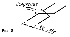
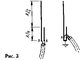
One of the simplest ZL-beam designs is shown in Figure 2. It contains two split half-wave vibrators (loop vibrators are often used) connected by an overhead line with crossed wires. Since the wave shortening coefficient in the overhead line is close to unity, then when the system is powered at the points "X-X", the phase shift of the oscillations in the vibrators just corresponds to the above formula. A more accurate phasing of the elements is achieved by changing (selecting) their length. In this case, the resonant frequency of the element changes and, like any oscillatory circuit, in accordance with its phase-frequency characteristic, the phase of oscillations in it. Strictly speaking, power can be supplied even to the middle of the line, and the phasing of the elements can be carried out in this way: one element is slightly shortened, and the other is slightly lengthened. The detuning of the elements is very small, since the required phase shift in each element is only f/2. The radiation pattern of the ZL-beam in the horizontal plane (in azimuth) is noticeably narrowed also because the vibrators themselves do not radiate sideways. In the vertical plane, the diagram is somewhat wider. This antenna is very good as a small-sized directional antenna with horizontal polarization. According to numerous data from the literature, its efficiency reaches 4 dB relative to a dipole or 6 dB relative to an isotropic (omnidirectional) emitter. For obvious design reasons, it is not very easy to position the ZL-beam vibrators vertically, in addition, there are problems with the wiring of the power line. In view of these difficulties, the author's thoughts turned to more suitable vertical radiators, which could be placed at a small distance from each other, in accordance with the ZL-beam ideology. One of these radiators is a J-antenna, two versions of which, differing only in the way they are matched to the feeder, are shown in Fig. 3.
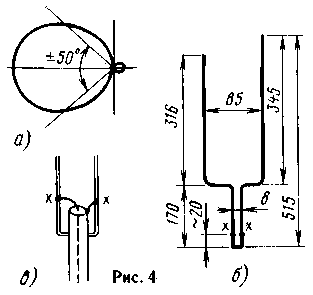
The J-antenna is a half-wave vertical vibrator fed from the lower end. At the end, the resistance of the vibrator is very high and reaches several kiloohms, in full accordance with Ohm's law - after all, the current here is small, and the voltage is high. To match it with a low cable resistance, a quarter-wave two-wire line is used. In the first variant (on the left in Fig. 3), its wave impedance should be equal to the geometric mean between the vibrator and cable resistances, i.e. anything in the region of 300 ... 600 ohms. Exact matching can be achieved by changing the wave impedance of the line (practically - the distance between the conductors). This is not entirely convenient, so the second version of the J-antenna (on the right in Fig. 3) is better in many respects. Here, the conductors of the quarter-wave line are simply closed at the lower end, and this point with zero potential can be grounded with a wire of any length, connected to any "mass", for example, the roof of a house or car, which is convenient constructively, but you can not connect anywhere at all. Power is supplied to the line by an autotransformer, at points "XX" located at a certain height above the short-circuited end of the line. With any cable, the antenna is easily matched by simply moving the "XX" feed points. The wave impedance of a two-wire line in this embodiment does not matter much. The further course of thought was as follows: if two J-antennas in a directional system are located side by side, is it possible to use one common two-wire line to power and coordinate them? After all, the voltages on the conductors of the open end of the line are antiphase, which is exactly what is required to power two closely spaced vibrators! Well, the necessary phase shift of oscillations in vibrators +f/2 and -f/2 can be obtained by changing their length - shortening one and lengthening the other. It remains to decide how to connect the ends of the half-wave vibrators, separated by L / 8, with the ends of the two-wire line, located side by side. It turned out to be easy - after all, the current is small at the ends of the vibrators, they almost do not radiate, so there will be nothing wrong if the ends of the vibrators are bent towards each other and directly connected to the ends of the line. Everything turned out incredibly simple, so much so that doubts arose - would it work? An experiment was needed. No sooner said than done, the antenna at a frequency of 430 MHz (wavelength 70 cm) was bent from a single piece of copper wire with a diameter of 1,7 mm. Its sketch with dimensions refined during the experiments is shown in Fig. 4 b).
The power cable with a wave impedance of 50 ohms was connected as shown in Fig. 4 c). It is useful to make the contacts at the "XX" feed points movable in order to select the position of these points according to the minimum SWR. Unfortunately, there was nothing to measure the SWR, and the position of the feed points was chosen according to the maximum of the antenna field in the main direction. A homemade field indicator was used, consisting of a dipole antenna, a diode detector, and a 50 µA measuring head. The signal source was a measuring oscillator with an output impedance of 50 Ω and an attenuator with a step of 1 dB. Initially, the antenna was fixed in a table vise for the lower base of the two-wire line, then a primitive swivel stand was made. Although the measurements were carried out in an unequipped room and do not claim to be highly accurate, the antenna fully met expectations! Firstly, the antenna worked and gave unidirectional radiation towards the short vibrator. Second, when compared to a half-wave dipole located in the same location and fed by the same cable, the oscillator attenuator had to be pushed in 4 dB to get the same signal on the field indicator. This allows us to evaluate the antenna directivity factor by the same figure. The radiation pattern in the vertical plane (the plane of the vibrators) is shown in Fig. 4a, and, in general, fully corresponds to the similar patterns of two-element beams. In the horizontal plane, the diagram is the same, but somewhat wider. It is curious that by adjusting the length of the elements, it is possible to achieve the complete absence of the back lobe (in any case, the field indicator did not detect it), but at the same time, the gain was somewhat, by a fraction of a decibel, less than when tuning the antenna to the maximum gain. In conclusion, we present some practical considerations on the design of the proposed antenna. To increase mechanical strength, you can install an insulator at the ends of a two-wire line, in the area of its bend and transition to the conductors of the vibrator. The insulator must be of good quality, since the antinode of the voltage is located here. The bends themselves do not have to be made at a right angle, the "shoulders" of the antenna can also be inclined. Moreover, it seems to the author that the position of the "shoulders" is not particularly critical - they can be located a little higher or a little lower. It is much more important to observe the full length of the conductors from the bottom of the two-wire line to the top end of the vibrator. It should be about 0,73L. for a short vibrator (director) and about 0,77L for a long one (reflector). With an increase in the diameter of the conductors (tubes) from which the antenna is made, their length decreases somewhat. The shortening factor for "thick" vibrators can be found in the antenna literature. We also note that there is no need to make vibrators and a two-wire line from tubes of the same diameter. The antenna will be stronger and will be better able to withstand wind loads if the two-wire line is made of tubes of a larger diameter, and the vibrators are made relatively thin. For the convenience of adjustment, it is useful to equip the vibrators with "topmasts" at the upper end, telescopically inserted into the main tube, since shortening the vibrators with wire cutters, as the author did, is fraught with irreversible consequences - after that, the vibrator can only be lengthened with a soldering iron. Author: Vladimir Polyakov (RA3AAE), Moscow; Publication: N. Bolshakov, rf.atnn.ru
Machine for thinning flowers in gardens
02.05.2024 Advanced Infrared Microscope
02.05.2024 Air trap for insects
01.05.2024
▪ Wireless HDMI Keychain for TVs ▪ Ultra-strong carbon nanotube nanowires ▪ Improving the efficiency of MRAM memory ▪ Cree XLamp XH Efficient Ceramic LEDs
▪ section of the site Intercoms. Article selection ▪ article Robot Orion. Tips for a modeler ▪ article Which legendary American president used emoticons in his notes? Detailed answer ▪ article Sikhote-Alin. Nature miracle
Home page | Library | Articles | Website map | Site Reviews www.diagram.com.ua |


 Arabic
 Bengali
 Chinese
 English
 French
 German
 Hebrew
 Hindi
Hindi Italian
 Japanese
 Korean
 Malay
Malay Polish
 Portuguese
 Spanish
 Turkish
 Ukrainian
 Vietnamese


 Leave your comment on this article: