|
|


 Arabic
 Bengali
 Chinese
 English
 French
 German
 Hebrew
 Hindi
Hindi Italian
 Japanese
 Korean
 Malay
Malay Polish
 Portuguese
 Spanish
 Turkish
 Ukrainian
 Vietnamese
|
ENCYCLOPEDIA OF RADIO ELECTRONICS AND ELECTRICAL ENGINEERING Antenna with active reflector. Encyclopedia of radio electronics and electrical engineering
Encyclopedia of radio electronics and electrical engineering / HF antennas Directional antennas of various types are widely used for long-range amateur short-wave communications. Relatively long ago, antennas of the "wave channel" type entered into practice, the simplest of which contain two elements - an active half-wave vibrator and a passive reflector. However, two-element antennas with a passive reflector do not provide satisfactory radiation directivity. If at the frequencies of television channels it is still possible to put up with the use of multi-element antennas, then for KB bands (even 28 MHz) they, together with a rotating device, are excessively bulky structures. In this regard, two-element antennas with an active reflector are increasingly being used. The fact is that antennas powered by a reflector have a number of advantages over antennas with passive elements. Briefly, these advantages are as follows. The gain of a two-element antenna with both active elements is equivalent to that of a full-size three-element antenna with a passive director and reflector. With the same values of the gain, the two-element system is lighter, structurally simpler and has a lower moment of inertia and windage. Antennas with active power allow you to get more suppression of radiation back, which in amateur communications is more important than obtaining the maximum gain values possible for a given system. At the same time, it should be noted that active-powered antennas are more difficult to tune and more critical to changing parameters. The principle of operation of a two-element antenna powered by a reflector is to create two anti-phase fields of equal amplitudes in the direction opposite to the main maximum of the system radiation. The use of an active reflector makes it possible to achieve equality of currents in both elements of the antenna and the phase difference necessary for maximum attenuation of the radiation back. Calculations carried out according to the well-known formulas of antenna theory [1] show that the gain of such an antenna is 3,4 dB higher than that of an antenna with a passive reflector, and the maximum suppression of back radiation (taking into account losses in the connecting line) is 40- 50 dB, while in passive systems it does not exceed 25 dB. The width of the diagram in the horizontal plane at the level of 0,707E is 58°, and the beam width in the vertical plane with a suspension height of l/2 and a radiation angle of 30° is 32°. The described two-element antenna with an active reflector is a modification of the HB9CV antenna [2, 3], the scheme of which is shown in fig. 1. With the optimal distance between the elements equal to l/8, anti-phase fields can be obtained by feeding the antenna elements with a phase shift of 225°. A phase shift of 225° in the power supply of the reflector is equal to the sum of the phase shifts that occur due to the anti-phase power supply system of the elements (180°) and the delay in the power line (45°).
It should be noted that the antenna circuit [2] contains erroneous data that does not provide the required phase shift when powered by a coaxial cable. The fundamental disadvantage of this antenna is the difficulty of obtaining the required phase shift, which is due to the selected power supply scheme. Any feeder line has a shortening factor associated with its design and materials used. For feeder lines used in antenna technology, the shortening factor is usually 1,05-1,66. Therefore, for the circuit in Fig. 1 when powered at points XX, instead of the required phase shift (due to the line) equal to 45 °, a value will be obtained depending on the type of line used. The scheme of the antenna, free from this drawback and allowing to obtain almost any phase shift between two active elements, is shown in Fig. 2.
The connection point of the supply feeder with a known line shortening factor can be easily determined by the formulas: dp+da=d+2Dlk, where d is the distance between the elements; da is the length of the line from the switching point to the antenna; dp - line length from the switching point to the reflector; Dlk - more constructive extension of the line (10-20 cm) and
where l is the working wavelength; y is the required phase shift; e is the shortening factor. To power the antenna, it is convenient to use a coaxial cable of the RK-75-7-11 type (for which e = 1,52) and a coaxial tee of the VR-193-F type, dividing the power equally between the vibrators. When using a tee, for better matching, it is necessary to use a coaxial cable with a characteristic impedance of 150 ohms (type RK-150-4-11 or similar) as connecting lines. When calculating the lengths of the elements of the antenna system (which are 0,5l for the reflector and 0,46l for the antenna itself), it is necessary to take into account their shortening factor, which depends on the diameter. The calculated values for an antenna with a diameter of 22 mm and a matching line with a diameter of 20 mm are given in Table. 1. The dimensions of the matching elements are also indicated here. Table 1
The dimensions of the blanks for the 14 MHz band antenna are given in Table. 2. Table 2
The design of the antenna is shown in fig. 3. Each element is made of three sections, consisting of duralumin tubes of conjugated diameters, sliding one into the other.
Since the outer diameter of one tube is equal to the inner diameter of the second, the tolerance system does not allow one tube to be driven into another to a considerable depth. Therefore, a cut is made along a tube of a smaller diameter to a length of 400 - 500 mm, after which their reliable articulation is ensured. Particular attention must be paid to ensuring reliable electrical contact at the junction. Contact failure causes a noticeable deterioration in the electrical parameters of the antenna. To facilitate tuning, flexible tips made of AMTs-M alloy are put on the ends of the elements (Fig. 4).
The elements are fixed on an duralumin pipe with a diameter of 40-45 mm and a wall thickness of 2 mm. To give rigidity to the entire antenna system, it must be braced with a nylon line 1 mm in diameter (Fig. 5).
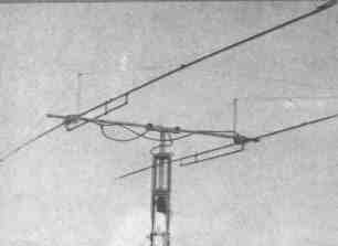
Other design features are visible from the photo. The antenna system weighs only 6,5 kg, making it easy for one person to mount the antenna.
To rotate the antenna, a PR-1 type electric motor with a potentiometric direction sensor mounted inside the housing was used. The antenna system is tuned based on the need to obtain the best matching of the antenna with the supply cable and maximum suppression of the back radiation. When setting up, it is advisable to use a signal from a local source located approximately in the plane of the elements at a distance of at least 150-200 m. The setup sequence is as follows. Determine the electrical length of the phase-shifting lines. The measurement and adjustment of this parameter must be carried out with an accuracy of at least 2-3 electrical degrees. By changing the length of the matching elements ya and yp, an acceptable SWR value of the entire system is achieved (not higher than 1,5 at the middle frequency of the range). By adjusting the lengths la and lр, the maximum suppression of the back radiation is achieved. At this stage, it is enough to achieve suppression of 20-25 dB. Measurements should be taken at several points in the range, after which y is re-adjusteda and yp, achieving an SWR value close to unity. These operations are performed sequentially several times until the best antenna parameters are obtained. It is desirable to make all measurements in the working position of the antenna in order to avoid the influence of the earth, which, at low antenna heights, can greatly distort the results. It should be noted that antennas with active elements have a known dependence of the back radiation suppression level on the elevation angle, which is determined by the difference in phase relations for waves arriving at different angles to the horizon. For long-distance communications, when these angles are insignificant, the suppression reaches 40-50 dB. Literature: 1. S. I. Nadenenko. "Antennas". Svyaztekhizdat, Moscow, 1959.
Author: A. Snesarev (UW3BJ); Publication: N. Bolshakov, rf.atnn.ru
Machine for thinning flowers in gardens
02.05.2024 Advanced Infrared Microscope
02.05.2024 Air trap for insects
01.05.2024
▪ Toshiba Efficient Thin Film Organic Photovoltaic Module ▪ Earth has its own mini-moons ▪ Forests do not save from excess carbon dioxide ▪ Cheap analogue of building sand from waste
▪ section of the site for the radio amateur-designer. Article selection ▪ article by Richard Bach. Famous aphorisms ▪ What was the result of the Reformation in England? Detailed answer ▪ article by Ferul Lehmann. Legends, cultivation, methods of application
Home page | Library | Articles | Website map | Site Reviews
www.diagram.com.ua | ||||||||||||||||||||||||||||||||||||||||||||||||||||


 Leave your comment on this article: