|
|


 Arabic
 Bengali
 Chinese
 English
 French
 German
 Hebrew
 Hindi
Hindi Italian
 Japanese
 Korean
 Malay
Malay Polish
 Portuguese
 Spanish
 Turkish
 Ukrainian
 Vietnamese
|
ENCYCLOPEDIA OF RADIO ELECTRONICS AND ELECTRICAL ENGINEERING Simple antenna and UHF converter. Encyclopedia of radio electronics and electrical engineering
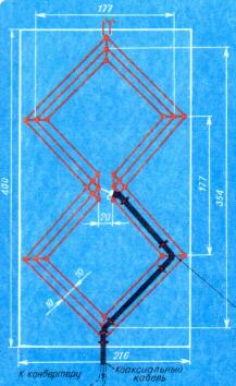
Encyclopedia of radio electronics and electrical engineering / Телевидение To receive television broadcasts in the decimeter wave (UHF) range, the owners of TVs equipped with the appropriate channel selectors use mainly indoor individual small-sized antennas. In this article, their attention is drawn to a simple broadband zigzag [1] antenna (see Fig. 1), which provides signal reception in any of the 21-40 UHF channels (470 ... 630 MHz). The antenna sheet is placed on a plate of transparent organic glass with a thickness of ''...5 mm. It is made of silver-plated copper wire with a diameter of 1,2 mm. At the connection points, the wire, passed through the holes in the plate, forms jumper brackets fixing the web.
The antenna is connected to the TV with a coaxial cable with a wave impedance of 75 ohms (for example, RK-75-3-31), laid along the sides of the canvas and attached to the plate with rings made of the same wire as the canvas, and inserted into the holes of the plate. The antenna is placed on a window frame facing the transmitting station (if this condition is not met, the reception quality deteriorates sharply). If there is no UHF channel selector on the TV, a converter is needed to receive transmissions in this range, which converts UHF signals into oscillations. received by the TV in one of the channels (1-12) of the meter band (MB). A schematic diagram of one of the options for such a converter, designed to work together with the described antenna, is shown in Fig. 2. In the middle position of the variable resistor R7, it consumes a current of 3.2 mA.
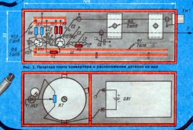
The converter consists of a local oscillator and a mixer. The local oscillator is assembled on a transistor VT1 according to a capacitive three-point circuit with feedback through a reverse-mixed diode VD1 [2], which simultaneously performs the functions of a converter setting element. When moving the slider of the variable resistor R7, the current through the transistor VT1 changes, and, consequently, the reverse voltage across the diode VD1 and the tuning frequency of the local oscillator resonant circuit, which is the unbalanced strip line L1. The local oscillator signal through the resistor R2 goes directly to the base of the transistor VT2 of the mixer, which made it possible to do without an additional strip line and ensure the stability of the mixer to self-excitation. The signal received by the UHF antenna also enters the base of the same transistor through the capacitor C2. The differential frequency voltage is amplified by the transistor VT2, allocated by a matching circuit L2C3R6 and is connected via a coaxial cable with an XW2 plug at the end to the input of the TV operating on one of the free (3-5) MB channels. The supply voltage from the GBI battery ("Krona", "Korund", etc.) is supplied to the converter through the RK-75-3-31 coaxial cable (braid and center conductor) and the input terminating resistor (75 Ohm) of the TV. At the same time, the HLI LED indicating that the converter is switched on lights up. To turn it off, just remove the plug from the antenna input of the TV. The converter uses resistors SP-1 (R7) and MLT (the rest), capacitors KPKM (C3) and Ml 500 or M750 (the rest). Coil L2 is wound on resistor R6 and contains 12 turns of PEL wire 0,27 with a tap from the middle. The details of the converter are placed on a printed circuit board made of double-sided foil fiberglass 2 mm thick (see Fig. 3). The connections of the terminals of the elements with the foil are shown by dots. Connections of two to four pins not marked by them are located above the board.
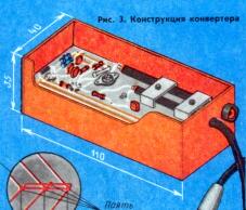
Printed conductors on the board are cut with a cutter 1,3 mm wide. Pieces of tinned copper wire with a diameter of 1...0.8 mm are inserted into holes with a diameter of 1 mm and carefully soldered on both sides. Cases of transistors VT1 and VT2 are installed in holes with a diameter of 6 mm. The connecting cables are pressed (using M3 screws) to the board with U-shaped metal brackets. The side walls of the converter are made of plates of one-sided foil-coated getinax, facing the inside of the case with foil and soldered to the board on both sides along the entire perimeter (see Fig. 3). In the upper compartment of the case, about 17 mm deep, there is a baffle soldered to the board and plates of the case. To it and to the body of the converter are soldered the output of the cover and the bent mounting protrusions of the variable resistor R7. The HL1 LED is inserted into the hole in the end wall. The compartment is closed with a lid with a hole for the resistor slider. Both converter covers are fixed with adhesive PVC insulating tape. The design of the converter is shown in fig. 4.
Setting up the device begins with checking the operation of the local oscillator. To do this, an avometer operating in the current measurement mode is connected to the XW2 plug. During normal operation of transistors VT1 and VT2, the currents in the extreme positions of the variable resistor R7 engine should vary from 2,4 to 4,4 mA. The normal operation of the local oscillator can be judged by the change in current when the tip of a screwdriver or tweezers touch the output of the collector of transistor VT1 in any position of the resistor R7 slider. Having done the above operations, the converter is connected to a TV set connected to one of the free channels (3-5) of the MB range. The variable resistor engine R7 is set to the middle position and, by moving the jumper along the L1 line, the converter is roughly tuned to the UHF program received on this channel. The board shows the approximate position of the jumper for receiving on channels 3-5. If you want to set the converter to one of the 6-12th channels, the jumper is moved to a position close to that shown in Fig. 3 dashed line. To receive programs outside the UHF coverage area, the antenna must be installed on a mast outside the house. To reduce losses in the feeder, a converter should also be placed next to it. As a result, the MB signal will be transmitted through the feeder to the TV input. The supply voltage to the converter in this case is supplied through the same feeder. Options for power supply switching circuits are shown in fig. 5.
Literature
Author: M. Ilaev Moscow, P 2/88; Publication: N. Bolshakov, rf.atnn.ru
Alcohol content of warm beer
07.05.2024 Major risk factor for gambling addiction
07.05.2024 Traffic noise delays the growth of chicks
06.05.2024
▪ Inexpensive protection of automotive electronics from cyber attacks ▪ Transcend StoreJet 35T3 8TB External Drives ▪ LMZ10501 - DC/DC nanomodule with load current up to 1 A ▪ Associated gas will burn profitably
▪ site section Preamplifiers. Article selection ▪ article by Ogden Nash. Famous aphorisms ▪ article How does Macropinna microstoma fish protect its eyes? Detailed answer ▪ article European white fir. Legends, cultivation, methods of application ▪ article Booster for electric guitar. Encyclopedia of radio electronics and electrical engineering ▪ article Electrization of the soap bubble. physical experiment
Home page | Library | Articles | Website map | Site Reviews
www.diagram.com.ua |

 Leave your comment on this article: