|
|


 Arabic
 Bengali
 Chinese
 English
 French
 German
 Hebrew
 Hindi
Hindi Italian
 Japanese
 Korean
 Malay
Malay Polish
 Portuguese
 Spanish
 Turkish
 Ukrainian
 Vietnamese
|
ENCYCLOPEDIA OF RADIO ELECTRONICS AND ELECTRICAL ENGINEERING Transceiver YES-98. Encyclopedia of radio electronics and electrical engineering
Encyclopedia of radio electronics and electrical engineering / Civil radio communications Published with abbreviations The YES-98 transceiver was originally conceived as a weekend design, but in the process of working on it, quite original circuit solutions were found that made it possible to create a relatively simple, portable, small-sized transceiver with the following main parameters:
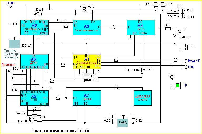
The transceiver operates in SSB mode on 1,9 bands; 3,5; 7; fourteen; 14; 21 MHz from both car and mains power supply. It uses a single conversion with an intermediate frequency of 28 MHz determined by the selected crystal filter. The block diagram of the transceiver is shown in Fig.8,82.
The transceiver consists of 7 blocks with the minimum required number of controls. In the receive mode, the signal from the antenna input through the attenuator (A5) and the three-circuit DFT (A6, Fig. 3), switched by diodes, is fed to the receiver mixer (VT1) in the block (A1, Fig. 2). The operation of such a mixer is described in detail in [I]. The IF signal, selected by the circuit L1, C4, is fed to the reversing IF amplifier (VT4) and then to a quartz filter of the FP2P4-410 type (from the Quartz-35 set). With the help of L2, C15, C16 and L3, C20, C22, less than 1 dB filter passband ripple is achieved. Circuit switching is carried out by diodes VD2 ... 4, VD11 type KD409. Further, the filtered IF signal passes through C42 to the input of the IF amplifier in the K174XA10 chip. The amplified signal is isolated by the L8, C31 circuit and then, together with the 8,82 MHz reference oscillator signal, is fed to the SSB input of the detector - to the 14th leg of the IF chip. From the output of the detector, a low-frequency signal is fed through the volume control to the input (pin 9) of a low-frequency amplifier and then to phones or to a speaker. At the same time, the signal from the detector is fed to the AGC amplifier (VT10 ... 12), the sensitivity of which is regulated by resistor R45. To increase the depth of the AGC, a transistor VT7 was introduced. An S-meter device is connected to the VT12 emitter, which displays the received signals with levels from S3 to S9 +20 dB with sufficient accuracy. The AGC voltage acts on the gates of the transistor VT4 of the reversing amplifier (VT4). as well as to the second gate of the transistor (VT3), which is used as a switch for the RX / TX mixers. The first gate (VT3) receives a signal from the GPA (block A 2, Fig. 4). The GPA is assembled according to the classical circuit on a field-effect transistor VT1 (block A 2), where the KVS111 (VD3) varicap is used as a capacitive source-gate divider. Frequency tuning is carried out by a 20-turn variable resistor (R-VAR). Instead of relays that violate the thermal balance of the GPA, KD409 diodes are used to switch ranges. The GPA generates signals with a frequency of 15,82 MHz to 25,2 MHz, followed by division. The division factor for each range is indicated in the table in Fig. 4 (block A2). The GPA signal through the decoupling stage (VT2) comes to the digital frequency divider switch. The required frequencies of the GPA with a stable amplitude are amplified by transistors VT4, VT5 to a level of 4 - 5 V and fed to mixers RX - TX, as well as to the input shaper of the TsAPCh on transistors VT1, 2 (block A7, Fig. 3). To generate the "count, reset and write" signals in block A7, signals with a frequency of 1 and 2 Hz from the DD4 microcircuit, which is a quartz frequency divider oscillator, are used. From the outputs of the divider to 16 (block A7. DD1 chip), the signal in the code 1-2-4-8, at the end of the count, is rewritten to the DD2 memory chip, from where, in the same code, digital signals using the R-2R matrix form 16 steps of constant voltage , which through the smoothing filter R15, C3, R17 acts on the VD13 varicap, adjusting the frequency in order to stabilize it. The GPA tuning step is thus equal to 64 Hz. This means that the inaccuracy of tuning to the correspondent will, on average, be 32 Hz. In the transmission mode, the signal from the microphone, amplified by the VT9 transistor (block A1), is fed to the input of a balanced modulator assembled on the K174URZ chip, Fig. 2. On the same chip, a quartz reference oscillator and a DSB preamplifier are assembled. In TX mode, the voltage on the cont. 7 of the K174URZ chip is zero, which leads to the appearance on the cont. 8 signal DSB, which with the help of VT8 is amplified and highlighted by the circuit 1.3, C20, C22. After the SSB quartz filter, the signal is fed to the first VT4 gate, where it is amplified in power and, using the coupling coil, is separated in the LI, C4 circuit, from where it is fed to the VT2 gate, which together with VT3 forms the TX mixer. At this time, VT1 is securely closed with a voltage of -2V between gates and source. The generated range signal is selected by the corresponding DFT circuits (block A6, Fig. 3) and with a level of 150 ... 200 mV is fed to the VT2 preamplifier (block A5, Fig. 5), from the output of which the amplified signal is fed to a push-pull driver assembled according to the classical circuit on transistors VT VT2 (block A3, Fig. 5). Further, the signal is amplified in power by a push-pull broadband amplifier on VT5 and VT6, which provides good linear amplification of SSB signals. You can get acquainted with this amplifier in detail and [2] Fig.2. Block A1 - The main board of the transceiver "Yes-98" (49 Kb) Fig.3. Blocks A6 - bandpass filters and A7 - DPKD (48 Kb) Fig.4. Block A2 - GPD 44 Kb) Fig.5. Blocks A3 - PA, A4 - SWR meter, A5 - TX driver and attenuator (40 Kb) In view of the small overall dimensions of the transceiver and the heat sink (radiator) of the power amplifier (PA), as well as to avoid overheating, the maximum output power is limited and does not exceed 50 W at a load of 50 Ohms. The power is limited by resistor R5 (block A3, Fig. 5). From the PA output, the amplified signal passes through a low-pass filter (LPF) with a cutoff frequency of 33 MHz - Cl, L1, C2, C3 L2 (block A4, Fig. 5) and then through the SWR meter and relay contacts RS1 is fed into the antenna (block A5, Fig. 5). One low-pass filter at the PA output turned out to be quite enough, due to the fact that the output signal has a low level of harmonics. In the process of working on the air, interference with television was not observed. In TX mode, the meter is connected to an SWR meter to indicate the transmitted power, or SWR. Transistor VT 1 and diode VD3 (block A4, Fig. 5) in the TX mode reduces the voltage at the gates of transistors VT3 and VT4 (block A1, Fig. 2) at elevated SWR values, forming an ALC system. Its efficiency is so high that it allows an open or short circuit in the antenna circuit at maximum power output. The transceiver is switched from RX to TX mode and vice versa using the keys VT5, VT6 (block A1), which form the control voltages + RX and + TX. Details and design of the transceiver The "Yes-98" transceiver is a rather complicated device and for its assembly it is desirable to have complete design documentation and printed circuit board drawings. Due to limited space, the collection is not given. A set of drawings can be obtained from the author, his address is at the end of the article, approx. R W3A V. The design of the transceiver is block, the chassis is made of sheet duralumin 4-5 mm thick. Elements of blocks Al, A2, A3 are mounted on printed circuit boards from double-sided fiberglass, and blocks A4, A5, A6 and A7 - from single-sided fiberglass. When designing independently, it should be noted that the contours of the printed conductors of the A2, A4, A5, A7, A3 boards (the contours of the tracks with smooth bends) are shown from the side of the parts, so they must be transferred to the blanks of the boards in a mirror image. On board A2, the foil from the side of the parts is left in the compartment where microcircuits DD1 ... DD3 and transistors VT4, VT5 are installed (block A2, Fig. 8). The GPA board - (block A2) is sealed in a tin box with removable covers. On the A6 (DFT) board, all capacitors of the filter circuits are installed on the side of the tracks. DPF coil frames are made from disposable 2 ml syringes. The frame for the GPA coil L1 is ceramic. All coil frames of the Al block are smooth, 15 mm long and 6,5 mm in diameter. 1 turns of PEV-2 wire are wound on frames (with brass cores) L45 and L0,2. The communication coil of the circuit L1, C4 has 4 turns of PEV-0,31. Coil L5 is wound in two wires and contains 15 turns of PEV-0,31. All chokes are used type DM. Transformer T1 (block A5, Fig. 1) is wound with PEV-0,31 wire on a 1000NN K12x5x5 ring and contains 2x8 turns. Driver transformer T1 (block A3, Fig. 5) is wound with PEV-0,31 wire on a 1000NN K12x8x6 ring and contains 3x9 turns. Chokes L1 and L2 are ferrite tubes from DM chokes 10 mm long, put on wires going to R4. Transformer T2 is made in the form of "binoculars" from 4 rings 1000NN K 12x5x5 and contains 3 turns of MGTF wire with a tap from the middle. The T3 transformer is wound on two rings 1000NN K12x5x5 and contains 2x8 turns of PEV-0,67 wire. The output transformer T4 is also "binoculars" and is made up of 6 rings 1000NN K 12x5x5, the output winding contains 3 turns of MGTF wire 1 mm thick. The DR2 inductor contains 20 turns of PEV-0,67 wire wound on a 1000NN K 12x5x5 ring. The transformer of the SWR meter T1 is wound on a 1000NN K12x5x5 ring and contains 28 turns of PELSHO-0,31, evenly wound around the entire circumference of the ring. Transceiver setup To set up the transceiver, you will need some electronic measuring instruments. At a minimum, you will need a high-frequency oscilloscope, a frequency response meter and a home-made device for determining the linearity of the radio frequency path - "Dynamics". The transceiver setup starts with the GPA block (block A2). When selecting the capacitors included in the oscillatory circuit, the generated frequencies are placed in the desired range, while not forgetting about thermal stability, taking into account the TKE of the capacitors used. By changing C22 and R22 within certain limits, an output voltage of about 5 V is achieved on all ranges. Then, using the frequency response meter (X1-48), tune the DFT (block Ab) by connecting a 10 kΩ resistor and a 15 pF capacitor to its output, and, of course, the XI-48 detector head. By selecting loop capacitors, and changing the distance between the coils, we achieve the desired frequency response with an unevenness of 1 dB. Setting up the main board (block A1, Fig. 2) must be started by setting the frequency of the reference oscillator to the lower slope of the quartz filter using L4 and C24. Then, by applying the GPA signal to pin B4 and the signal from the GSS to pin B2, you should tune the IF circuit to the frequency of the quartz filter. By connecting the Al block to the A6 block, the tuning of all resonant circuits is refined. The sensitivity from the antenna input should be about 0,15 µV. By applying a signal from the Dynamics device to the transceiver input, adjusting the RX mixer mode using resistor R43 and adjusting the cores of the L1, C4 and L2, C 15, C 16 circuits, achieve a dynamic intermodulation range of 90 dB. By adjusting R46 and R45 (block Al) the S-meter of the transceiver is calibrated. In the transmission mode, resistors R44 and R50 (block Al. Fig. 2) balance the modulator to a carrier suppression level of at least -50 dB, controlling the level of its balance on the L1, C4 circuit. When pronouncing a loud "AAA" in front of the microphone, at the output of the DFT at a load of 50 ohms on all ranges, the voltage should be at least 0,15 ... 0,2 V. Then the power is connected to the PA (block A3) and the quiescent currents are set by resistor R3 in the driver - about 80 mA and resistors RIO, R15, R16 in the output amplifier - about 200 mA. Having unbalanced the modulator, by selecting R10, C4 (block A5); R4, C4, Sat, C 14, C 15 (block A3), you should achieve the same output power at a load of 50 ohms (at least 50 W) on all ranges (nonsense RW3AY). Further, in the TX mode, the SWR meter is balanced and the measuring device (S-meter) is calibrated, which shows the transmitted power or SWR value during transmission. By disconnecting and shorting the antenna, the resistor R3 (block A4) should bring the output power to a safe mode. By connecting the "Dynamics" device to the input of the preamplifier of the broadband PA, the oscilloscope controls the linearity of the envelope of the two-frequency signal at the corresponding load. The CAFC block (block A7) is tuned by selecting resistors R15 and R17, while changing, respectively, the speed of response to a change in the frequency of the GPA and the degree of influence of the CAFC on frequency stability. The tuned transceiver in terms of the quality of receiving stations on the overloaded evening bands of 40 and 80 m is not inferior to more solid "brothers", both home-made and imported. An eloquent example is the following circumstance. A transceiver with an 80-meter delta antenna, located at a distance of 200 m from a well-established transmitter of a collective radio station with a power of about 1 kW, operating at 40 m with a delta band antenna, with a detuning of 5 - 10 kHz and the attenuator turned off, allows work quietly on the air. Naturally, the presence of a powerful station is felt by a small "splatter". Literature 1. "KB - magazine" No. 3 1994, pp. 19-26. Author: G.Bragin, Samara region Chapaevsk; Publication: N. Bolshakov, rf.atnn.ru
A New Way to Control and Manipulate Optical Signals
05.05.2024 Primium Seneca keyboard
05.05.2024 The world's tallest astronomical observatory opened
04.05.2024
▪ The main molecule of the Universe is determined ▪ Electrons flow like a liquid ▪ Acer Predator X34 Gaming Monitor
▪ section of the site Audio Art. Article selection ▪ article Dark people. Popular expression ▪ article Can a person turn gray in a minute? Detailed answer ▪ Article Halong Bay. Nature miracle ▪ article AF power amplifier (80 watts). Encyclopedia of radio electronics and electrical engineering
Home page | Library | Articles | Website map | Site Reviews
www.diagram.com.ua |

 Leave your comment on this article: