|
|
ENCYCLOPEDIA OF RADIO ELECTRONICS AND ELECTRICAL ENGINEERING Personal call in CB radio stations. Encyclopedia of radio electronics and electrical engineering
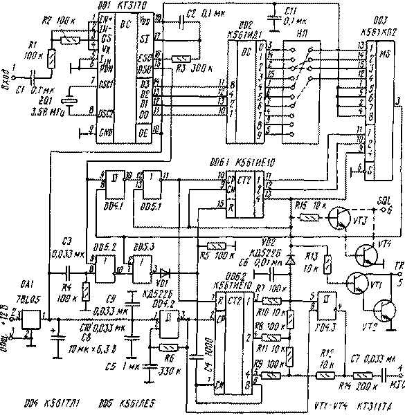
Encyclopedia of radio electronics and electrical engineering / Digital technology When organizing communication, for example, between a house and a summer cottage, the owners of CB radio stations often have a problem with calling a correspondent. In such cases, you either have to agree on communication sessions in advance, or constantly be near the radio station. To avoid such inconveniences, it is necessary to equip it with a paging system. One of the options for such a device is proposed in this article. Many VHF radio stations of foreign companies have noise suppressor control devices using a personal (selective) radio call (DTMF) decoder, as well as CTCSS signals. Such blocks also exist for CBS stations. But they, firstly, are relatively expensive, and secondly, they do not quite perform the functions of a personal call, that is, they simply open the squelch instead of giving a ringing signal. The author has developed a special DTMF, let's call it a PC decoder (Personal Calling Radio System). Connecting this device to a radio station allows, first of all, to eliminate the need to constantly listen to the channel while waiting for a call, especially if the channel is used by many correspondents, as it happens In most cases. When the radio station receives DTMF signals corresponding to the calling code to which the PC decoder is set, the device generates a sound signal on the dynamic head of the CB station of the station. At the same time, the station is switched on for transmission, and the correspondent hears a ringing signal for several seconds. This indicates that the call has been accepted by the subscriber. To transmit DTMF messages, you can use a beeper, which is applied to the microphone of the radio station on the transmitting side. The length of the transmitted code is four characters. The duration of the message must be at least 40...50 ms. The decoder sensitivity is 30...50 mV, and the input impedance is at least 100 kOhm. The device consumes a current of about 3 mA. The schematic of the PC decoder is shown in Figure 1.
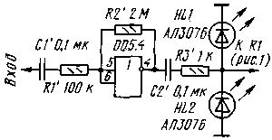
The basis of the device is a single-chip DTMF receiver (DD1) KT3170 from SAMSUNG (domestic analogue - KR1008VZH18), designed specifically for communication with moving objects, paging systems, remote control systems, etc. Thanks to the use of integrated filters on switched capacitors and a digital detection algorithm signal receiver has stable characteristics when the temperature changes in the range from - 40 to + 85 ° C. When the power is turned on, the initial setting pulse from the output of the DD5.2 element through the DD5.3 element resets the counter of the number of parcels DD6.1 to zero. If, for some reason, at input 2 of the DD5.3 element, a high level from the output of the DD3 multiplexer, then a low level from the output of the DD5.1 element allows the operation of the one-shot counter DD6.2, which counts pulses from the generator on the Schmitt trigger DD4.2. When DD6.2 passes from state "7" to state "8", the counter is blocked at the CN input by a high level from output 8. The differentiating circuit C4R5 generates a reset pulse for counter DD6.1. When a dual-frequency DTMF message arrives at the input of the receiver DD1, a binary code appears at its outputs DO-D3 corresponding to the transmitted digit. At the same time, a gate pulse is generated at the DSO output (high level for the time that a DTMF signal is received). Let's take access code 4226 as an example. If the code at the input of the decoder DD2 corresponds to the first digit "4", a high level occurs at its output 4, which, through the installed jumper, goes to input 1 of DD3. Since the counter DD6.1 is in the zero state, the output of the DD3 multiplexer is connected to input 1 (pin 13 DD3) and a high level will also appear on it. Element DD4.1 opens, and the signal from the DSO output, passing DD4.1 and DD5.1, resets the counter DD6.2 and keeps it in this state during the duration of the DTMF message. At the end of it, the level at the output of the element DD5.1 changes from high to low, i.e., a counting difference is supplied to the input of the CP counter DD6.1. The counter status increases by one and becomes equal to 0001 (output 1 is high). Thus, the multiplexer DD3 is prepared to receive the second digit, and the counter DD6.2 starts counting the pulses of the generator DD4.3, following with a period of 0,3 ... 0,4 s. Now, if within eight periods of the generator (2,4 ... 3,2 s) the next digit of the code does not arrive (in our example, this is the number "2"), then the counter DD6.2 will count up to eight and reset DD6.1, as described above, bringing the device to its original state. If a digit other than "2" arrives, then at the input 2 of the DD3 multiplexer (pin 14), and therefore, at its output, a low level will remain and the signal from the DSO output of the DD1 receiver through the elements DD5.2 and DD5.3 will immediately reset counter DD6.1. After 3 seconds, the counter DD6.2 will also return to its original state. If the second digit of the DTMF message coincided with the second digit of the code, the counter DD6.2 is reset before reaching state 8, and DD6.1 goes into state 0010, preparing to receive the next digit. After the successful acceptance of all four digits, the DD6.1 counter enters the state 0100, i.e., a high level occurs at its output 13, which blocks the counter at the CN input and, in addition, maintains a low level at the output of the DD5.1 element, allowing those the most work counter DD6.2. At the same time, the VD2 diode closes and the blocking is removed from the ringing signal generator on the DD4.3 element, which, together with the counter DD6.2 and the resistor matrix R7 - R12, forms a musical phrase of eight sounds of different tonalities. From the output of the generator, the ringing signal is fed through the R14C7 circuit to the microphone input of the radio station. The radio station itself is switched to transmission mode using a key on transistors VT1, VT2, and the calling correspondent takes control of the call. After 2...3 s, the entire device returns to its original state. If desired, the ringing signal can be made single-tone. To do this, exclude the resistors R7-R11, and connect the left output of the resistor R12 according to the diagram to the output b of the DD4.3 element and to the anode of the VD2 diode. The frequency of the ringing signal is selected by resistor R13. The PC decoder board is installed inside the radio station and connected with five wires. Since the nominal supply voltage of the KT3170 microcircuit is 5V, the device is powered through a low-power integrated stabilizer DA1 type 78L05 (domestic analogue - KR1157EN502A). The input impedance of the PC decoder is at least 100 kΩ, so it can be connected directly to the AM or FM output of the detector. However, it is better to turn on the decoder after the audio preamp but before the volume control. When this is not possible, and the gain is not enough for stable operation of the decoder, you can assemble a preamplifier on a free NOR element, as shown in Fig. 2.
The gain should not be made too high, given that according to the passport data, the maximum input voltage of the DTMF signal should be no more than 1,5 V. To limit the input voltage to acceptable limits, a two-way diode limiter on the HL1 and HL2 LEDs is turned on at the output of the preamplifier.
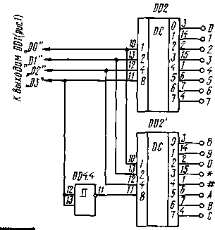
You can also increase the gain by selecting the resistor R2 (see Fig. 1) in the feedback circuit of the op-amp, which is part of the KT3170 microcircuit. The use of only one K561ID1 decoder in a PC decoder has a feature: unambiguous decoding of codes accepted in telephony is possible only for numbers from "1 ° to" 7 "and the letter" D ". When signals corresponding to the numbers "8" appear at the input, " 9", the letters "A", "B", "C" and the signs "*", "#", a high level occurs at the output 8 of the decoder DD2 for even, and at the output 9 - for odd combinations (see table) But the main trouble is that the DTMF receiver sets the output code not 0, but 0000 to the standard two-frequency message corresponding to the number 1010. The code 0000 corresponds to the letter "D". In other words, the DD2 decoder will work the same way as on the number "8", and on "C", "#" and "B". The same will be worked out "9", "*", "A", "C". Even if we restrict ourselves to a code consisting only of numbers, then "8" and "0" will be decoded the same way. This can be avoided by some complication of the device, as shown in Fig. 3. An additional decoder chip DD2' can be soldered on top of the main one. However, it is unlikely that there is a great need for such a complication, since the number of combinations of only eight digits ("1" - "7", "9") with a four-digit code is 8 to the fourth power, i.e. 4096 combinations. Naturally, there is an inconvenience if the operator wants to use his callsign number containing the numbers "8" or "0" as a code.
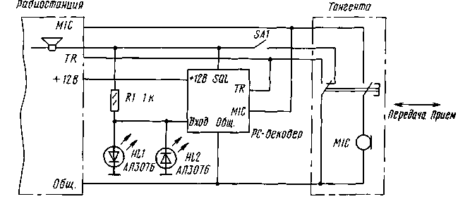
Before setting up the PC-decoder, the access code is programmed on the type-setting field of the NP. To do this, input 1 of the DD3 multiplexer is connected to the output of the DD2 decoder, corresponding to the first digit of the code, input 2 to the output corresponding to the second digit, etc. In fig. Figure 1 shows jumpers for access code 4226 as an example. Setting up the device begins with a DTMF receiver. If a branded ZQ1 quartz resonator is used at a frequency of 3,579545 MHz, then the adjustment comes down to checking the received codes for compliance with the table when DTMF messages are fed to the input, for example, from a beeper or generator assembled according to known schemes. It is permissible to use a telephone set with a "TONE-PULSE" switch as a generator of two-tone (DTMF) parcels. When using small-sized resonators at a frequency of 3,58 MHz from telephone sets, it may be necessary to connect two 30 pF capacitors. One capacitor must be connected between pin 7 of the DD1 chip and a common wire, and the second between pin 8 and a common wire. This is necessary to reliably start the DTMF receiver generator. Then, by selecting the resistor R6, the oscillation period of the generator on the element DD4.2 is set, which should be of the order of 0,3 ... 0,4 s. In this case, the maximum allowable pause between tonal bursts can be 2.. .3 s. The call will last the same amount and the call control signal will be transmitted. By selecting the resistor R14, the level of modulation during the transmission of the control signal is adjusted so that it is comparable with the signal from the microphone. The final check is carried out on the air when working with a correspondent. Another option for connecting a PC decoder to a radio station is shown in fig. 4. In this case, the PC decoder is connected between the radio and the PTT. The main advantage of this inclusion is that it is not necessary to open the radio station case. In addition, if the PTT is not equipped with a DTMF keyboard, then it, together with the DTMF signal generator, is placed in the PC decoder case. The resistance of the resistor R1 is many times greater than the resistance of the dynamic head of the radio station, therefore, in standby mode, almost no sound power is emitted on it. When the PC decoder is triggered, the key opens on transistors VT3, VT4 (Fig. 1) and the dynamic head is connected to the common wire, as in normal mode, giving almost full power. LEDs HL1 and HL2 protect the input of the DTMF receiver from overload. In the operating mode, the contacts of the SA1 toggle switch must be closed, and the dynamic head of the radio station is connected to the common wire through the "Receive / Transmit" switch of the PTT. This disables the PC decoder. In the call waiting mode, the SA1 toggle switch is moved to the position shown in fig. 4, and the volume control of the radio station is set almost to the minimum, but so that the decoder is triggered by a weak signal. This setting is carried out by the glow of the LEDs HL1 and HL2 while listening to correspondents. The radio squelch must be opened, after receiving the call SA1, it is transferred to the closed position and a communication session is conducted. Author: O.Potapenko, Rostov-on-Don; Publication: N. Bolshakov, rf.atnn.ru
Artificial leather for touch emulation
15.04.2024 Petgugu Global cat litter
15.04.2024 The attractiveness of caring men
14.04.2024
▪ Up to 4TB Seagate NAS Hard Drives for Network Attached Storage ▪ The body amplifies the sound ▪ Babies scream in different languages ▪ Vivo 2 Wireless Headset for Athletes
▪ section of the site Life of remarkable physicists. Article selection ▪ article by Jean Cocteau. Famous aphorisms ▪ Article At what temperature does water freeze? Detailed answer ▪ article ticket controller. Job description
Home page | Library | Articles | Website map | Site Reviews www.diagram.com.ua | ||||||||||||||||||||||||||||||||||||||||||||||||||||||||||||||||||||||||||||||||||||||||||||||||||||||||||||||||||||||||||||||||||||||||||||||||||||||||||||||||||||||||||||||||||||||||||||||||||||||||||||||||||||||||||||||||||||||||||


 Arabic
 Bengali
 Chinese
 English
 French
 German
 Hebrew
 Hindi
Hindi Italian
 Japanese
 Korean
 Malay
Malay Polish
 Portuguese
 Spanish
 Turkish
 Ukrainian
 Vietnamese


 Leave your comment on this article: