|
|


 Arabic
 Bengali
 Chinese
 English
 French
 German
 Hebrew
 Hindi
Hindi Italian
 Japanese
 Korean
 Malay
Malay Polish
 Portuguese
 Spanish
 Turkish
 Ukrainian
 Vietnamese
|
ENCYCLOPEDIA OF RADIO ELECTRONICS AND ELECTRICAL ENGINEERING Additional remote control for satellite receiver. Encyclopedia of radio electronics and electrical engineering
Encyclopedia of radio electronics and electrical engineering / Television, video equipment The author solved the problem of remote control of a satellite receiver from two different rooms by developing and manufacturing an additional simplified remote control on a microcontroller. It is suitable for use with devices equipped with IR remote control using the NEC protocol. The problem of controlling a satellite receiver using one remote control from two different rooms is well known to those who, for various reasons, did not spend money on an additional receiver. I also encountered this problem. In order to turn on the receiver or change the channel while in the kitchen, you had to go to the room where it was installed each time. After many such “trips”, it was decided to make an extension cord that would transmit IR commands from the kitchen to the room. Various publications have repeatedly published articles about such extenders that receive IR commands from the remote control in one room and repeat them in another. But even here there was an inconvenience: the remote control still had to be carried with you. To eliminate it, the idea arose to develop a homemade simplified remote control to control the receiver from the kitchen, equipped with only five buttons with which you can turn the receiver on and off, as well as sequentially cycle through channels in one direction and another. The remote control is constantly located in the kitchen, and its emitting diode is carried on wires into the room where the receiver is located, which executes the given commands.
But first, it was necessary to find out what protocol and what command codes were used by the main remote control of the HD IVR ready S-21 receiver. To observe the shape of the signals of the commands given to him, I did not make any complex devices, but used a phototransistor connected according to the circuit shown in Fig. 1, to the input of a digital oscilloscope. As VT1, you can use not only a phototransistor of the type indicated in the diagram, but also any other. For example, I successfully used an MP14B transistor made from germanium pnp by removing the housing cover. To do this, it was carefully crushed with side cutters at the base until it was completely separated. The result is shown in Fig. 2. The IR beam is directed at the crystal of the opened transistor from the emitter side. Instead of a phototransistor, you can also use a photodiode, for example, FD263.
From the captured oscillograms, you can determine what type of protocol the recorded pulse sequences belong to. A description of the main protocols used in remote control systems for household appliances can be found in the article by A. Torres “Infrared remote control” altor1.narod.ru/Articles/IRC.pdf. It turned out that the remote control of the "HD IVR ready S-21" receiver operates according to the NEC protocol, so the microcontroller program for the remote control being developed was written for this protocol.
The diagram of the additional remote control is shown in Fig. 3. Thanks to the use of the ATtiny2313 (DD1) microcontroller, it turned out to be very simple. In the initial state, when none of the SB1-SB5 buttons are pressed, the microcontroller is in sleep mode. In this state, the remote control consumes less than 1 µA of current, which allows it to be powered from the GB1 battery without a switch. When you press any of the buttons, the microcontroller goes into operating mode and generates a series of pulses that form the transmitted code. It consists of a long start pulse, an eight-bit address of the device to which the command is sent, and the command code itself of the same width. The address and command are transmitted twice - in direct and inverted form (Fig. 4). This allows the receiver to check whether the received message is corrupted, and also makes the total transmission duration the same for any combination of address and command. Finally, the generated sequence amplitude modulates the subcarrier - pulses with a repetition frequency of 38 kHz.
To generate pulses of this frequency, the microcontroller uses a timer/counter T0. It counts the 8 MHz clock pulses in the TCNT0 register. The contents of this register are compared with the number stored in the OCR0A match register. At the moment of a match, the counting register is reset to zero, and the state of the OC0A output (pin 14 of the microcontroller) is reversed, this happens every 13 μs. Modulation of the subcarrier with a code sequence occurs by software turning on and off the timer/counter T0. To generate a code sequence, the Send_Com (adr, cmd) function is intended, the parameters of which are the values of the address and command code. The first of them (adr) for controlling the satellite receiver "HD IVR ready S-21" is always set equal to 8, this is the address of this receiver in its remote control system. The address of other receivers may be different, it must be found out during the above-described study of the code messages transmitted by the remote control being replaced . The second parameter (cmd) is the actual command code. In the case under consideration, when different buttons are pressed, it is set in the program in accordance with Table. 1. Table 1
The number of commands supplied by the remote control in question can be increased from five to eight - this is exactly the number of pins, by changing the level at which the ATtiny2313 microcontroller can wake up from sleep mode, its port B has. To add commands, the upper (according to the diagram) pin of resistor R1 should be moved from pin 14 to pin 9 (PD5) of the microcontroller and install three more buttons in the device, connecting them to pins 12-14 (PB0-PB2) and the minus supply voltage. Table 2
In the file nec_protoc.c you need to find the main function and make changes to its initial fragment (initialization section) in accordance with table. 2. Three conditional statements similar to those given in table are added to the body of the infinite loop while(1){} that follows this section. 3. They differ only in that in each of them, instead of PINB.7, the state of one of the inputs (PINB.0, PINB.1, PINB.2) to which additional buttons are connected is checked, and the cmd parameter of the Send_Com function is the command code, submitted when the corresponding button is pressed.
Having made all the changes, the program must be translated again, and the resulting HEX file must be loaded into the microcontroller. If you need a remote control capable of issuing more than eight commands, you will have to replace the microcontroller, for example, with an ATmega88. Upon completion of the command transmission, the sleep_enable function switches the microcontroller to power_down mode with a very low current consumption, which is important for battery-powered remote controls. The microcontroller will exit this mode only by the next press of any button. When pulses arrive from pin 14 of the microcontroller (or pin 9 if the program is modified) to the base of transistor VT1, a pulse current flows through the emitting diode VD1. The command is transmitted “on the air”. The resistance of resistor R2 is selected depending on the maximum distance of diode VD1 from the photodetector of the receiver. It should be taken into account that for a emitting diode of the type indicated in the diagram, the current in a pulse with a duration of no more than 100 μs should not exceed 200 mA.
The printed circuit board of the remote control is shown in Fig. 5. All parts are placed on it, with the exception of diode VD1. They are mounted on the side where there are more printed conductors. Short pieces of tinned wire are inserted and soldered on both sides into the via holes shown filled in in the drawing. If desired, the printing can be made one-sided by replacing the printed conductors connecting the vias with the button contacts with jumpers made of insulated wire. Almost any npn transistor with h1a > 21 and Ikmax > 100 mA can be used as VT100. The TSAL6200 emitting diode can be replaced with a domestic one, for example, AL107A or AL107B. Capacitors - any small ones with a capacity of 12...22 pF. Resistors - MLT or imported.
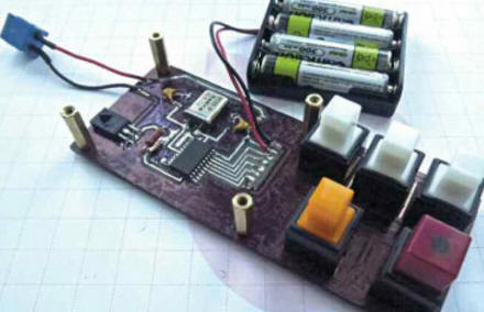
The finished remote control is shown in Fig. 6. A compartment with three galvanic cells or four AA-size batteries, forming the GB1 battery, is attached to a textolite plate installed above the board on metal stands. In this form, the remote control is placed in any convenient and accessible place to control it. The emitting diode VD1 is carried on long wires into the room where the controlled receiver is located, and is placed so that there is direct visibility between this diode and the photodetector of the receiver. The program is loaded into the FLASH memory of the microcontroller using any programmer capable of working with microcontrollers of the AVR family. It is written in C and compiled in the Code VisionAVR system. The remote control does not require any setup and, if installed correctly, starts working immediately. The printed circuit board file in SprintLayout5.0 format and the microcontroller program can be downloaded from ftp://ftp.radio.ru/pub/2013/10/RC.zip. Author: I. Chukharev
Traffic noise delays the growth of chicks
06.05.2024 Wireless speaker Samsung Music Frame HW-LS60D
06.05.2024 A New Way to Control and Manipulate Optical Signals
05.05.2024
▪ Sculptures from the bottom of the Rhone
▪ section of the site Mobile communications. Article selection ▪ article Table of Ranks. Popular expression ▪ article What future awaits our luminary - the Sun? Detailed answer ▪ article The functional composition of Thomson TVs. Directory
Home page | Library | Articles | Website map | Site Reviews
www.diagram.com.ua |


 Leave your comment on this article: