|
|


 Arabic
 Bengali
 Chinese
 English
 French
 German
 Hebrew
 Hindi
Hindi Italian
 Japanese
 Korean
 Malay
Malay Polish
 Portuguese
 Spanish
 Turkish
 Ukrainian
 Vietnamese
|
ENCYCLOPEDIA OF RADIO ELECTRONICS AND ELECTRICAL ENGINEERING How to connect a joystick from a game console to a computer. Encyclopedia of radio electronics and electrical engineering
Encyclopedia of radio electronics and electrical engineering / Телевидение Fans of computer games began to connect the familiar and convenient joysticks from video game consoles to their computers since 1999, when the DirectPad Pro software package, distributed free of charge via the Internet, appeared to serve them. But it often happens that a fully functional joystick refuses to work with a computer. The author proposes his own solution to this problem, also providing a useful opportunity in many games to increase the number of joysticks simultaneously connected to the computer. Joysticks from game consoles are connected to the computer's parallel port LPT1 or LPT2 through adapters of just a few small diodes. On the Internet, it is easy to find wiring diagrams for joysticks from the consoles "Atari", "TurboGrafX-16", "Genesis" ("Sega Mega Drive-ll"), "NES" ("Dendy"), "PlayStation" (including the joystick " DUAL SHOCK"), "SuperNES", "Sega Master System", "Nintendo-64", "Sega Saturn", 'Jaguar', "Virtual Boy". The joysticks themselves do not require any alteration and work, as a rule, without an external source nutrition. The most common joysticks in the CIS countries are from "Dendy", "PlayStation" and "Sega Mega Drive". The latter, unfortunately, are fundamentally incompatible with some recent computer motherboards. Joysticks of the first two types are successfully used by numerous gamers who have installed the DirectPad Pro package on their computers. But sometimes joysticks that normally interact with a game console refuse to work when connected to a computer. In addition, when several joysticks are connected to the LPT port at the same time, it is impossible to do without an external power source. There are two main reasons for this. Firstly, the load capacity of the LPT-port lines used to power the joysticks is insufficient. Already under load 3 ... 4 mA level log. 1 (taking into account the voltage drop across the diodes of the adapter) drops below the minimum necessary for the operation of the joystick microcircuit - 3 V. Secondly, the thyristor effect characteristic of CMOS microcircuits appears - a sudden sharp increase in the current consumed. The latter phenomenon is associated with the opening of a usually reliably closed "parasitic" thyristor, formed inside the microcircuit by sections of a semiconductor crystal of various conductivity. It becomes possible if the voltage at the logic input of the microcircuit exceeds the supply voltage, and occurs, as a rule, at the moments of power-up or "hot", without turning off the power, reconnection of connectors. It is these situations that arise when the joystick is connected to the LPT according to the "standard" scheme. The voltage at its logic inputs is increased, since, unlike the power output, they are directly connected to the port lines, without isolation diodes and do not consume noticeable current from them. The situation is aggravated by the blocking capacitor usually present in the joystick power circuit and discharged at the moment of switching on. It must be said that not all CMOS microcircuits are subject to the thyristor effect to the same extent. It is typical, for example, for microcircuits KR537RU10, KR1146FP2, but rarely appears in such common series as K561, KR1561 and many others, manufactured using special techniques - guard rings, MOSFETs with a vertical channel and ring gate, SOS technology (silicon on sapphire). Improved schemes for connecting joysticks from game consoles to the LPT port are shown in fig. 1 (for "Dandy") and Fig. 2 (for "Sony PlayStation") In contrast to the prototypes distributed via the Internet, in both cases, conventional silicon diodes VD1-VD5 are replaced by Schottky diodes, similar diodes VD6-VD11 are reintroduced and increased accordingly to five and two connectors for joysticks Of course, if you don't plan to use that many joysticks at the same time, the "extra" connectors can be eliminated.
The cathodes of all previously existing and newly introduced diodes are connected in parallel. Thus, the joystick is powered by all port lines on which the log level is set or can be set programmatically. 1. Of course, the load is unevenly distributed between the lines, the main share of the current is given by the one on which the voltage is slightly higher than on the others. However, the possibility of simultaneously powering five "Dendy" joysticks or two "PlayStation", including "DUAL SHOCK", has been experimentally confirmed. Diodes VD7, VD8 (see Fig. 1) or VD7-VD9 (Fig. 2) also perform an additional function - they protect the joystick chip from the thyristor effect, preventing the voltage at its inputs from rising above the supply voltage by more than the direct voltage drop across Schottky diode. This voltage never exceeds that at which a "normal" p-n junction inside the microcircuit can open, which can provoke a thyristor effect. The X1 plug that is connected to the socket of the LPT port of the computer in both versions of the adapter is DB-25M. Diodes VD1 - VD11 are placed inside the body of the plug, soldered directly to its contacts and well insulated with segments of a PVC tube of suitable diameter. Numbers of pins of connectors X2...X6 in fig. 1 are for DB-9M plugs that mate with "narrow" joystick cable outlets. If it is necessary to connect a joystick with a "wide" socket, the DB-9M plug is replaced with a DB-15M plug, taking into account the differences in the pin assignments indicated in the table. As X2-X6, you can also use plugs from faulty video set-top boxes.
The last option is almost the only one for "PlayStation" joysticks, since sockets suitable as X4 and X3 (Fig. XNUMX, view from the side of the sockets) can only be found in a faulty video set-top box. If there is none, you will have to use separate sockets of the right size, put on the corresponding pins of the cable plugs.
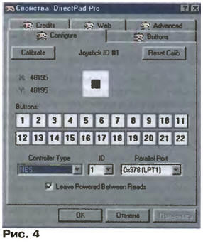
The length of the wires connecting the adapter to the sockets (plugs) of the joysticks should not exceed 1 m. It is better to use a ribbon cable. If you limit yourself to connecting one joystick, the connector for it can be installed on the body of the X1 plug. You can even refuse the connector altogether by soldering the wires of the joystick cable directly to the contacts of the X1 plug and the terminals of the diodes VD1 - VD11. Naturally, such a joystick can no longer be connected to a video set-top box. For full-fledged operation of "DUAL SHOCK" joysticks with vibration feedback, it is necessary to apply a voltage of 2 V from an external source to connector X2 (see Fig. 7,5), which is not required for joysticks of other types. The source must be designed for a current of at least 0,5 A (for each joystick). Sometimes it is recommended to increase the voltage to 9 V, which significantly enhances the recoil effect. However, as a result, the vibrator winding overheats. Without external power, the DUAL SHOCK joystick remains operational, but the vibration feedback does not work. As diodes VD1 - VD11, in addition to those indicated in the diagrams, KD923A or other small-sized Schottky diodes are suitable. In extreme cases, conventional KD522B can also be used, but this will increase the likelihood of unstable operation of some joysticks. All diodes must be of the same type. Diodes VD6, VD9 ... VD11 (see Fig. 1) or VD6, VD10, VD11 (see Fig. 2) can not be installed if this does not lead to failures. Communication between joysticks connected to the computer's LPT port and game programs provides DirectPad Pro package. The package was developed by Earle F. Philhower III in 1999. Its drivers run under Windows-9x using the DirectInput instruction set of DirectX 5.0 and later. As a result of installing the DirectPad Pro package, a new gaming device will appear in the system - the "DPP joystick". Install DirectPad Pro in the following order. After creating a separate folder (for example, under the name DPP) and unpacking the dpadpr50.zip archive into it, it is necessary, following the scheme "My Computer" - "Control Panel" - "Game Controllers" - "Add" - "Add" - "Install from disk", tell the folder name to the operating system of the computer. In the list of files that appears, point to DirectPad Pro.inf, double-click "OK" and select the DirectPad Pro Standard And Force FeedBack device. Next, find DirectPad Pro Controller (for "Dendy" and regular "PlayStation" joystick) or DirectPad Pro Force FeedBack Controller (for "DUAL SHOCK" joystick) in the list of gaming devices. By clicking the "Properties" button, select the controller - NES for "Dendy" or one of the five options suggested by the computer (usually PSX Digital or PSX Left Analog) for "PlayStation". It remains to specify the identification number (ID) of the joystick (1 - for the first of the installed ones, in ascending order - for the subsequent ones) and the address of the LPT port to which it will be connected. You can find out the port address using the scheme "My Computer" - "Control Panel" - "System" - "Devices" - "COM and LPT Ports". It remains to calibrate the joystick by pressing its buttons and observing the movements of the black rectangle inside the white square in the "Configure" tab of the "Properties" window (Fig. 4). In case of failures, in the "Advanced" tab of the same window, increase the value of the PSX Scan Delay parameter from 3 to 10. There you can also select the Sine, Ramp, Const, Spring parameters that provide the best feedback effect in the DUAL SHOCK joystick.
Most programs that simulate video set-top boxes on the IBM PC support DPP joysticks. You can "download" free console emulators, for example, from the site . In principle, using the DPP joystick, you can control the operation of any computer program. There are several free emulators for this, for example, joyemu41 (by Simone Zanella). After installing any of them, all operations that were previously performed using the "mouse" can be performed using the DPP joystick. Addition When connecting a joystick from a Sega video set-top box to an LPT port according to the scheme recommended by the author of the DPP package, modern IBM-compatible computers, unlike their obsolete versions, do not respond to pressing the UP / Z and DOWN / Y buttons of the joystick. According to this scheme (in the file called genesis.gif) these buttons are connected to the STROBE and AUTOFEED lines of the LPT port, the state of which is displayed by bits 0 and 1 of the printer control register. For a programmer, this is port37AH (LPT1) or 27AH (LPT2). An explanation of the reason for the incompatibility could not be found on any Internet site. I had to carefully study the device of the LPT-port adapters of personal computers of various generations. On fig. 1a shows a typical diagram of the input and output circuits of one bit of the control register of the "old" LPT adapter used in the IBM PC / XT, in their clones and in some computers of later generations. The open-collector output of inverter DD1, loaded with resistor R1, is directly connected to the connector pin. The inverter input DD2 is also connected here. With the standard use of the register to output printer control signals, the logic level at the output of the DD2 element repeats the input of the DD1 element, and the level at the X1.1 connector pin is inverted.
The "Sega" joystick software driver uses "forbidden reception". Log entry. 0 in the corresponding bit of the control register at the output of the element DD1 is set to a high voltage level. In this state, the output transistor of the inverter DD1 is closed and does not affect the operation of the node. Connected to the pins of connector X1, the button of the joystick SB1, when pressed, will connect the input of the inverter DD2 to a common wire. As a result, reading the computer processor control register will give a 0 in the corresponding bit when the button is released and 1 when it is pressed. In modern computers, the input and output circuits of the control register are built according to a different scheme, shown in fig. 1,6, and the elements DD1.1-DD1.3 are, as a rule, inside the LSI. The logic of the standard (output only) operation of the node remains the same, but the technique described above no longer works. Therefore, the computer does not respond to pressing the UP / Z, DOWN / Y buttons of the joystick. An improved scheme for connecting a joystick from a Sega video set-top box to a computer is shown in fig. 2. It has three differences from the original. Firstly, the signal from the DOWN / Y button is applied to the previously free contact 15 (ERROR) of the X1 plug. Secondly, transistors VT1 and VT2 are introduced, the bases of which are supplied with signals from the UP / Z and LEFT / X buttons, and their collectors are connected to each other and to pin 10 (ACKNLG) of the X1 plug. The emitters of the transistors are connected respectively to pins 1 (STROBE) and 14 (AUTOFEED) of the X1 plug. Thirdly, a VD8 diode has been added, which reduces the likelihood of a "thyristor" effect in the joystick's CMOS chip.
The position of the DOWN/Y button is now displayed in bit 3 of the printer status register at address 379h for LPT1 or 279h for LPT2. In bit 6 of the same register, depending on the voltage levels set by software on the emitters of the transistors, the position of the UP / Z or LEFT / X button is displayed. For example, if pin 1 is low and pin 14 is high, transistor VT2 is permanently closed, and VT1 is open when high and closed when low on the UP/Z line. When the levels on pins 1 and 14 are inverted, transistor VT1 will be permanently closed, and VT2 will be open at high and closed at low level on the LEFT/X line. The joystick is powered by the VCC circuit through the VD1-VD8 isolation diodes from eight lines of the LPT port, seven of which (pins 3-9 of the X1 plug) have a high logic level at all times. The current consumption of the joystick depends on the number of simultaneously pressed buttons and, as a rule, does not exceed 2...4 mA. The joystick supply voltage does not go beyond 3,5 ... 3,8 V (VD1-VD8 - Schottky diodes indicated in the diagram) or 3,1 ... 3,4 V (ordinary silicon diodes). All elements of the transition device can be placed inside the plastic housing of the 25-pin DB-25M plug (X1) by soldering their leads directly to the contacts. The DB-9M plug (X2) is connected to the rest of the elements by a flat nine-wire cable or a bundle of stranded insulated wires with a cross section of at least 0,2 mm2 and a length of no more than 1,5 m. Resistors - any small-sized. The ratings of two of them (R1 and R3) are non-critical and can range from 22 to 82 kOhm. Transistors - KT315, KT312, KT3117 with any letter indices or other silicon low-power np-p structures. Do not use transistors - with an ultra-high (more than 250) value of the coefficient h21E. Diodes with a Schottky barrier 1N5819 can be replaced with similar ones KD923A. If you install ordinary silicon diodes, for example, KD522B, the joystick supply voltage will decrease, as a result of which some instances may malfunction. Changes have been made to the dpadpro.vxd and dpadpro.dll files of the DPP version 5.0 package to adapt to the new way of connecting the joystick from the "Sega" set-top box. The upgraded package (version number changed to 6.0) is packaged in the dpadpr60.zip archive, where the C++ folder also contains the source code for the new joystick poll routine. When installing a new package on your computer, use the recommendations of the article mentioned above by selecting the "Genesis" controller (joystick with UP, DOWN, LEFT, RIGHT, A, B, C, START buttons) or "Genesis 6 button" (added buttons X, YZ, MODE). When working with joysticks from other video consoles, the new version is no different from the original 5.0. If an incorrect reaction of the computer to pressing the joystick buttons is detected during calibration, the reason lies, as a rule, in the installation errors of the matching device. The DPP package is designed to work in a Windows-9x environment. For Windows-2000/XP operating systems, an additional "NTPAD XP" driver is required. DPP software package version 6.0. Author: S.Ryumik, Chernihiv, Ukraine
Alcohol content of warm beer
07.05.2024 Major risk factor for gambling addiction
07.05.2024 Traffic noise delays the growth of chicks
06.05.2024
▪ New way to remove hydrogen from silicon surface ▪ The lawn mower runs on grass and is guided by Google maps ▪ Unmanned aerial vehicles with biohull ▪ 450 mm wafers and hard UV lithography
▪ section of the site Metal detectors. Article selection ▪ article Help with fractures, dislocations, bruises and sprains. Occupational Safety and Health ▪ article Where did church choir members survive by being late to class? Detailed answer ▪ article Dogrose wrinkled. Legends, cultivation, methods of application
Home page | Library | Articles | Website map | Site Reviews
www.diagram.com.ua |


 Leave your comment on this article: