|
|


 Arabic
 Bengali
 Chinese
 English
 French
 German
 Hebrew
 Hindi
Hindi Italian
 Japanese
 Korean
 Malay
Malay Polish
 Portuguese
 Spanish
 Turkish
 Ukrainian
 Vietnamese
|
ENCYCLOPEDIA OF RADIO ELECTRONICS AND ELECTRICAL ENGINEERING A simple economical metal detector. Encyclopedia of radio electronics and electrical engineering
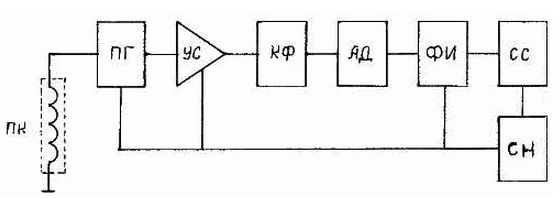
Encyclopedia of radio electronics and electrical engineering / metal detectors The proposed device compares favorably with previously published metal detectors of this class in terms of energy efficiency, increased sensitivity and simplified signaling. The proposed metal detector detects magnetic and non-magnetic metal objects in the ground, in the wall of a building at a depth: a coin of 25 kopecks - 10 ... 15 cm, larger objects - up to 60 cm. Simplified signaling makes it possible to focus more on the search area. The disadvantages of the proposed device include: the slow drift of the frequency of the search generator, which is typical of this class of metal detectors. The block diagram of the metal detector is shown in fig. one.
When metal objects act on the PC search coil, the frequency of the PG search generator increases. The frequency-changing PG signal is amplified by the US amplifier. The amplified signal is fed to the KF quartz filter. When the frequency of the PG coincides with the resonant frequency of the CF (the absence of metal near the PC), the signal passes to the amplitude detector of the blood pressure, is converted into a constant component, which forms a log pulse in the pulse shaper FI. "1". Log. "1" affects the CC alarm system and no chime is generated. When metal objects appear in the PC search coil area, the PG generator changes the frequency, as a result of which a log appears at the SS input. "0", and the alarm starts working as long as there are metal objects in the PC zone. All necessary elements of the circuit are powered by a voltage stabilizer CH. The current consumption of the device is up to 8,5 mA. The schematic diagram is shown in fig. 2.
The search generator is made according to the capacitive three-point circuit with a common base on the transistor VT1, the load of which is the coil L1 and the input circuit C5R3 of the signal amplifier, made according to the emitter follower circuit on the transistor VT2. The amplified signal from the resistor R5 is fed to the quartz filter ZQ1. The signal of the search generator with a frequency equal to the resonant frequency of the quartz filter is fed to the amplitude detector, made on diodes VD1 and VD2. The detected signal in the form of a constant component is fed to the base of the transistor VT3 - FI. A current flows through the resistor R7, creating a voltage drop across it, and forms a log. "1" at input 1 DD1.1. At the same time, a log is fed to input 2 DD1.1. "1" from output 4 DD1.2. At this moment, the single vibrator, made on the elements DD1.1 and DD1.2, is closed and there is a log at output 3 DD1.1. "0". The multivibrator, made on the elements DD1.3 and DD1.4.B, this moment does not work together with the emitter BQ1. When the search coil L1 approaches a metal object, the frequency of the PG increases regardless of the "color" of the metal. The PG signal with an increased frequency goes beyond the limits of the ZQ1 quartz filter. The absence of a signal at the output of ZQ1 leads to the locking of the FI, and a log appears on 1 DD1.1 of the one-shot. "0". The single vibrator DD1.1 and DD1.2 is triggered, and a log appears at its output 3 DD1.1. "1", which, in turn, starts the multivibrator DD1.3 and DD1.4. Emitter BQ1 starts emitting an audio frequency signal. With a short-term loss of the signal after the quartz filter (fast movement of the PC), the duration of the emitter BQ1 will depend on the value of the capacitance of the capacitor C10. In the proposed device, the alarm works instantly and with "memory". For hard of hearing people, you can install the VD3 LED, connected in the diagram with dotted lines. In this case, the current consumption of the device will increase. The voltage regulator DA1 simplifies the voltage stabilization circuit for the purposes of the device circuit. Details. All resistors type MLT 0,125 W. Tuning capacitor C1 type 1KPVM or other type with an air dielectric. .In the absence of such, you can use a small-sized variable capacitor with a solid dielectric from pocket radios with a capacity of up to 50 pF. If there is no such capacitor, you can use a larger capacitor, including in series with it a capacitor of constant capacitance of the required size. It is desirable to use capacitors of the C2-C4 circuit with a negative TKE group, for example, M47-M750. You can try to mix the M and PMO groups. Capacitor C2 can be taken from the circuit diagram of small-sized radio receivers. Small-sized quartz resonator from 100 kHz to 1 MHz. In this case, the number of turns of the search coil L1 will have to be selected for the corresponding resonator. Piezoelectric emitter BQ1 made in China from small phones or watches. You can use a domestic radiator type 3P-1, but it is larger and consumes more power. The entire electronic part of the device is mounted on a printed circuit board made of one-sided foil fiberglass 1,5 mm thick. A control board made of the same material is soldered to the end of the board at an angle of 90 °, on which the tuning capacitor C1 and the small-sized switch SA1 are installed. In the author's version, the board the size of a matchbox is placed in a rectangular aluminum box (screen of the IF circuit from the "Kazakhstan" radio receiver). The rod is made of a sanitary tube made of aluminum and covered inside and out with a plastic sheath with a diameter of 16 mm. The search coil L1 is made as follows: a circle with a diameter of 150 mm is drawn on a board or thick plywood. At the intersection points of the chords, drive in metal studs 20 mm long at an angle of 45 ° with an inclination away from the center of the circle. On the resulting template, wind the coil L1 with a wire PEV-2, PELSHO with a diameter of 0,31 ... 0,47 mm. In the author's version, the coil is wound with LESHO 10x0,07 wire - 15 turns. After winding the L1 coil, do not cut the end of the wire, as you may have to wind or unwind it during adjustment. Strip the ends of the coil and solder to the connecting cable. The number of turns in your version can be approximately calculated in proportion to the author's one using the quartz resonator you have. After winding the coil and fixing its ends, the turns of the coil are fixed by tying several turns of thread and fixing them with a knot. Such fastening is carried out around the entire perimeter of the coil through two studs, after which the studs are pulled out. Coil connection cable L1 can be shielded. In the author's version, a shielded wire is used, covered on top with a plastic sheath with a diameter of 1,2 mm. You can use a conventional flexible installation wire, tightly twisted to stabilize its capacity. After setting up the entire device and adjusting the number of turns of the search coil, it is inserted into a PVC tube of the appropriate diameter, cut on one side along the entire length in one plane. The length of the tube should exceed the circumference of the coil by 5 mm, the ends are overlapped on the coil. Lead out the coil connection cable at the junction of the PVC tube. In the future, this place will be a gap between the shielding coating. Try to keep within the size, docking of the tube and cable outlet, in 5 ... 10 mm. Place the coil laid in the tube on a flat surface with the cut up. Place newspaper underneath. Sequentially spreading the tube section with a screwdriver, fill the space in which the coil is located with the prepared epoxy glue. Places of buckling or divergence of the walls of the tube must be fastened with threads. It is better to choose a PVC tube stored in round rolls of the desired diameter. After cutting such a tube, its walls will diverge less. After the polymerization of the epoxy glue (in a day), the coil must be cleaned from drips, the threads must be removed to make the surface smooth. A shielding layer of copper or brass foil 8...10 mm wide and 0,05...0,1 mm thick is wound on the smooth surface of the coil. Its purpose is to eliminate the capacitive influence of the earth and other objects on the parameters of the search coil. It is necessary to start winding the shielding layer from the PVC tube joint and finish winding from the other end of the PVC tube joint. The gap between the beginning and end of the shielding layer can be 5...20 mm. In no case should you connect the beginning and end of the shielding layer, as a short-circuited coil will result. One of the ends of the shielding layer is connected to the coil terminal and the shielding layer of the connecting cable. The shielding layer of the L1 coil along the inner perimeter is soldered along the entire length with a solder width of 5 ... 10 mm. In many publications, the shielding layer of the search coil is proposed to be made of aluminum foil. During the author's tests of several designs of search coils with an aluminum foil screen, the following shortcomings were revealed:
Some publications suggest that the shielding layer of the search coil be wrapped with PVC tape. When testing several coils coated in this way, it turned out that when the temperature or mechanical loads changed, the parameters of the search coil changed. This is due to the fact that it is not possible to wind the tightly shielding layer manually. Under the action of the elasticity of the PVC tape, when exposed to temperature and other factors, the gaps between the shielding layer foil and the coil change, and with them the parameters of the search coil. To eliminate the above disadvantages, the shielded coil was placed in a cut PVC tube and filled with epoxy glue. The finished coil is attached to a crescent-shaped textolite plate with the help of thick threads passed through holes drilled in the plate at the places where the coil fits. The places where the coil is attached to the textolite plate and the fastening bandages made of threads are smeared with epoxy glue. The plate with the reel is attached to the rod bent at the end in the form of a "stick" in the middle with a clamp made of a sheet of brass, steel, aluminum 30 mm wide and 0,5 ... 1 mm thick. The clamp around the perimeter is tightened with two M3 bolts. The unbent paws of the clamp are attached to the textolite plate of the coil with the help of 2, 4 M3 bolts. The connecting cable of the coil is passed into the inside of the rod and connected to the electronic unit through the hole. The battery "Krona" is located under the electronic unit and secured with a rectangular clamp. The metal detector together with the Krona battery weighs 300 g. Establishment. Connect the device to a 9 V power supply through a milliammeter. The milliammeter should show a current of 8mA. Emitter BQ1 must emit a low frequency signal. By adjusting the resistor R9, achieve maximum volume. To turn off the alarm, you must disconnect the output 1 DD1.1 from the circuit or resistor R7. Instead of capacitor C2, connect a variable capacitor 0 ... 500 pF. It is better to use a dual capacitor 2x500 pF with an air dielectric for adjustment. Connect the "unfinished" search coil to the circuit through a connecting cable of a certain length. Connect the oscilloscope to the VT2 emitter. An RF component with a level of about 3 V should appear on the screen. Connect a digital frequency meter to the VT2 emitter and determine the frequency of the search generator. Set the variable capacitor C1 to the middle position. Using a tuning capacitor, set the frequency of the search oscillator equal to the frequency of the ZQ1 quartz resonator. If the frequency of the search generator is higher and it is impossible to lower it with a tuning capacitor, connect the second section of this capacitor in parallel with the tuning capacitor. If this operation did not help to reduce the frequency of the PG to the resonant CF, then it is necessary to wind up several turns of the PC. If, on the contrary, the frequency of the PG is low and the adjusting capacitor fails to increase it, then it is necessary to unwind several turns from the PC. After comparing the frequencies of the PG and the CF, connect the oscilloscope to the output of the CF at the connection point of VD1 and VD2. Set the slider of the resistor R5 to the upper position. If ZQ1 is working and the PG is adjusted, a picture of the RF component should appear on the oscilloscope screen. With the resistor R7 connected, a log should appear on the emitter VT3. "1", i.e. voltage 2,4 ... 5,7 V. When the SS is connected, the emitter should be silent. The number of turns of the PC should be chosen so that the capacitance of the capacitor C2 is approximately 50 pF. With further refinement of the PC, i.e. applying a shielding layer, pouring epoxy resin, attaching to a rod, the inductance of the coil will decrease. To do this, before the complete completion of the manufacture of the PC, add another 2-4 turns. After the completion of PC manufacturing, it is necessary to re-adjust and determine the capacitance value C2 using a capacitance meter. In the absence of the above devices, the presence of SG generation can be determined by the constant component on R5 by disconnecting and connecting capacitor C3. The presence of coincidence of the PG frequency with the CF can be determined by the constant component at R7 and the work of the SS. It is possible to determine the value of the capacitance of the capacitor C2 empirically by the position of the rotor of the adjusting capacitor. During the final adjustment, it is necessary to tune the PG to the resonant frequency with the CF using the capacitor C1 until the emitter stops sounding. In this case, the capacitance of the capacitor C2 must be such that the frequency resonance occurs at the middle position of the tuning capacitor C1. We turn the slider of the resistor R5 "down" to the end, and the alarm should go off. Turn the R5 slider back until the alarm signal disappears and a couple more degrees. For final adjustment after complete assembly, it is necessary to drill a hole in the device case to adjust the resistor R5. It must be remembered that the maximum sensitivity of the metal detector will be at the frequency of the PG, located on the edge of the upper bandwidth of the CF. When metal objects appear in the PC area, the frequency changes "up" by units, tens of hertz, depending on the size of the search objects and the PC distance from them. When setting the PG to the lower bandwidth of the CF, the impact of metal objects on the PC will lead to the restructuring of the PG to the middle bandwidth of the CF, which will not trigger the SS. Based on the above, it is better in a device to have an "up" drift that automatically increases sensitivity before an alarm is triggered than a "down" drift that reduces sensitivity for a long time. Therefore, in the SG circuit it is better to use capacitors with negative TKE or together with negative and positive TKE. Literature
Author: B.N.Dubinin, Novoyavorivsk, Lviv region
Artificial leather for touch emulation
15.04.2024 Petgugu Global cat litter
15.04.2024 The attractiveness of caring men
14.04.2024
▪ Alternative to silicon for microcircuits ▪ The electric car is charged through the antenna ▪ Mold has learned to feel gravity ▪ The tablet will be able to control an unmanned truck
▪ section of the website Basics of First Medical Aid (BFA). Selection of articles ▪ Armageddon article. Popular expression ▪ article Which spiders feed mainly on plant foods? Detailed answer ▪ article Stone valerian. Legends, cultivation, methods of application ▪ article Chemical watchman. Chemical experience
Home page | Library | Articles | Website map | Site Reviews
www.diagram.com.ua |


 Leave your comment on this article: