|
|


 Arabic
 Bengali
 Chinese
 English
 French
 German
 Hebrew
 Hindi
Hindi Italian
 Japanese
 Korean
 Malay
Malay Polish
 Portuguese
 Spanish
 Turkish
 Ukrainian
 Vietnamese
|
ENCYCLOPEDIA OF RADIO ELECTRONICS AND ELECTRICAL ENGINEERING Block for satellite reception. Encyclopedia of radio electronics and electrical engineering
Encyclopedia of radio electronics and electrical engineering / Television antennas The device described in this article solves two problems. Firstly, it allows you to connect several users to one antenna, and secondly, it makes it possible to receive programs that IC3 transmits with different polarizations on one antenna. As you know, in the same frequency range of satellite direct broadcasting (START), signals are transmitted with both vertical and horizontal polarization. They can be received on one antenna, supplementing it with orthomode converters with separate vertical and horizontal polarization outputs. Such a device can be made independently from two simple converters with a rectangular waveguide, the cost of which in the CIS markets is currently 3-5 dollars. The orthomode splitter consists of three parts: an input waveguide of circular cross section with waveguide-coaxial junctions and two rectangular waveguides with flanges for connecting converters of vertical and horizontal polarizations. Probes located at an angle of 1o relative to each other are installed in the input waveguide (Fig. 19) of circular cross section with a diameter of 90 mm.
An incident wave of vertical or horizontal polarization, entering a circular waveguide, induces an EMF on the submersible part of the corresponding probe, which is transmitted via a coaxial line to the radiating part of the probe, made in the form of a cylinder 4 mm in diameter, soldered to the end of the probe pin. The immersion probe V (for vertically polarized signals) is installed at a distance of 9 mm from the end wall of the circular waveguide and is located parallel to the electric field lines of the incident electromagnetic wave with vertical polarization, as a result of which an EMF is induced on it. With respect to a wave with horizontal polarization, pin V is located perpendicular to the lines of force of the electric field, and no EMF is induced on it. For a submersible probe H (i.e., signals of horizontal polarization), the reverse picture of the electromagnetic field is observed: an EMF is induced on it only from a wave with horizontal polarization. Thus, there is a splitting of two coupled waves with vertical and horizontal polarizations. The radiating parts of the probes are located inside two rectangular waveguides (Fig. 2) attached with M2,5 screws to the side faces of the round waveguide.
Moreover, one of the waveguides is bent at an angle of 90" in accordance with Fig. 3.
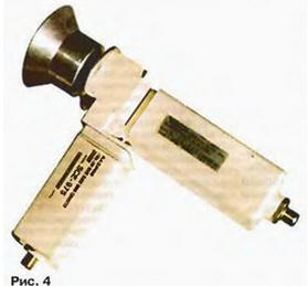
The radiating parts of the probes are installed at a distance of 7,5 mm from the end wall of the rectangular waveguides. Thus, the radiation of the electromagnetic wave H10 in a rectangular waveguide is carried out. For better matching with a rectangular waveguide and increasing the bandwidth of the coaxial waveguide transition, the radiating part of the probe is made with a matching coaxial resistance transformer in the form of a brass cylinder 4 mm in diameter, 2,2 mm long and a submersible probe soldered to the end of the pin. The assembled waveguide device is connected to two SNV converters in the range of 10,9...11.7 GHz (10,7...12,05 GHz) with rectangular waveguides 9,5 x 19 mm in size. The appearance of the assembled orthomode converter with independent outputs of vertical and horizontal polarizations is shown in fig. 4.
To connect such a converter to the antenna, feeds for direct-focus or offset antennas, similar to those shown in Fig. 6 and 7 in the article "CTB Converter"(" Radio ", 1999, No. 3, p. 8; No. 4, p. 14). To reduce the noise factor of the converters in their microwave amplifiers, the input stage transistors were replaced by ATF36077 transistors from Hewlett Packard. This made it possible to achieve a noise figure of about 0,7 dB when using converters with an initial noise figure of 1,1...1,5 dB. An orthomode converter mounted on the antenna (Fig. 5) with V and H polarization outputs (A1, A2) is connected to power dividers (A75, A4) with coaxial cables PK3-4.
Transformer dividers ALDA 1...1250 MHz (A3, A4) used for power division in the decimeter range were used as power dividers into three channels. Measurements have shown that when these dividers are used in the range of 0,9...1,8 GHz, the reflectance of the divider input does not exceed 0,3, which is considered quite acceptable for START systems. Outputs 1, 2 and 3 of the power dividers A3 and A4 are connected with a coaxial cable PK75-4 to the inputs of the START signal switches (A5, A6, A7). The switch diagram (all three are identical) is shown in fig. 6. Switching of the input signals of H and V polarizations connected to the connectors XW1, XW2, is carried out by switching the supply voltage of the converters from 13 to 18 V. When the +3 V supply voltage is applied to the XW13 connector, the zener diodes VD1 and VD2 are closed and the voltage drop across the resistor R1 is zero. Transistors VT1 and VT2 are closed, and the voltage at the input XW1 is zero.
The switching diode VD6 is closed, and the incident wave from the XW1 input to the XW3 output does not arrive. Since the transistor VT3 is also closed, the transistors VT4 and VT5 are open and from the collector of the transistor VT5, through the protective diode VD4, the +12 V voltage is supplied to the XW2 power connector of the vertical polarization converter. At the same time, the VD5 diode opens and the intermediate frequency (IF) signal from the output of the V polarization converter through the capacitor C2 and the open diode VD5 enters the XW3 connector and then to the input of the STV tuner. When the supply voltage is switched to +18 V, the zener diodes VD1 and VD2 open and a voltage of +1 V appears on the resistor R3. Transistors VT1, VT2 and VT3 open, and VT4 and VT5 close. The +1 V power supply of the H-polarization converter is supplied to the XW17 input. The switching diode VD5 closes, and the diode VD6 opens, and the IF signal of the H-polarization converter through the capacitor C1 and the diode VD6 is fed to the output of XW3 and then to the input of the STV tuner. The device for switching signals of IF converters of V and H polarizations is made on a printed circuit board made of one-sided foil fiberglass 1,5 mm thick (Fig. 7) and placed in a metal screen made of tinned brass, on the side walls of which connectors XW1, XW2, XW3 type F75 are fixed for connection of the tuner and power dividers A3, A4. Inductors L1 - L5 are frameless coils with an inner diameter of 2 mm, wound with a piece of PEL 0,15 wire 80 mm long. Capacitors C1 and C2 - type KD1, C3 - type KM-5, KM-6. Resistors - MLT-0,125. In addition to the indicated types of transistors, the following can be used: instead of KT3102VM - KT315B1, KT342BM; instead of KT502BM and KT502VM - KT814A, KT814B, KT814V, KT816A, KT816B, KT816V, KT873A, KT873B; instead of KD514A diodes, KD512A or KA517A are applicable. Two KS175A zener diodes are completely interchangeable with one KS515A1 zener diode in a glass case.
The adjustment of an orthomode splitter is reduced to the selection of the length of the submersible parts of the probes of coaxial waveguide junctions. On fig. 1 shows the maximum length of the pins. When adjusting the transition, the pins immersed in the round waveguide are gradually shortened by 0,5 ... 1 mm until the best image quality is obtained on the channel with the lowest signal level. Setting up the switch (Fig. 6) is reduced to the selection of zener diodes VD1, VD2 so that the comparator switching threshold is 15 V. Author: V. Zhuk, Minsk, Belarus
Artificial leather for touch emulation
15.04.2024 Petgugu Global cat litter
15.04.2024 The attractiveness of caring men
14.04.2024
▪ Human fear recognition service ▪ SpaceX capsule reused for the first time ▪ Malarial mosquitoes sense toxins ▪ Wind farms could work on Mars
▪ section of the site Microphones, radio microphones. Article selection ▪ article Damaging factors of a nuclear explosion. Basics of safe life ▪ article What is the smallest bird in Britain? Detailed answer ▪ article Datura vulgaris. Legends, cultivation, methods of application
Home page | Library | Articles | Website map | Site Reviews
www.diagram.com.ua |


 Leave your comment on this article: