|
|
ENCYCLOPEDIA OF RADIO ELECTRONICS AND ELECTRICAL ENGINEERING Tuningless circuits for transmitters. Encyclopedia of radio electronics and electrical engineering
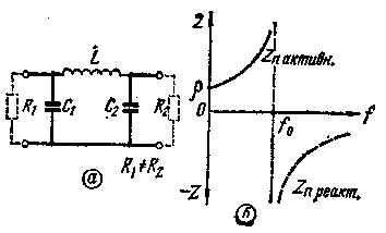
Encyclopedia of radio electronics and electrical engineering / Knots of amateur radio equipment. Filters and matching devices Most shortwave transmitters use a P-loop in the output stages of transmitters. By its structure, the P-loop is a low-pass filter of the "K" type, operating between unequal load resistances (Fig. 1, a). Such a filter significantly attenuates signals whose frequency exceeds its resonant frequency. For example, the suppression of the second harmonic of the main signal is approximately 20 dB. The suppression of low-frequency signals is somewhat worse, and occurs mainly due to the uneven characteristic impedance of the P-loop. When designing transmitters for single-sideband communication, methods of successive conversions are used. In this case, in addition to the main signal, side signals with frequencies both higher and lower than the main signal may appear.
The second disadvantage of the P-loop is the frequency dependence of its tuning. As can be seen from fig. 1b, the characteristic impedance of the circuit changes especially strongly near its resonant frequency, which leads to the need to adjust the circuit even within the same range. When moving to another range, it is necessary to change the values of all elements, and therefore such circuits usually have three settings. When using modern well-matched antenna-feeder devices, it becomes possible to make the transmitter output circuits non-tuning. If we consider the L-shaped half-link of a band-pass filter of the "K" type (Fig. 2, a), then we can see that within the passband, the characteristic impedance of the filter is active and changes little depending on the frequency (Fig. 2, b). However, this filter contains two inductors and also requires that the load resistances be equal, which is not feasible in real conditions.
Bandpass filter elements are calculated using the following formulas:
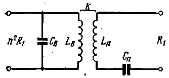
Through successive conversions, the bandpass filter can be converted into a transformer filter (Fig. 3).
where L1, L2, С1 and С2 are calculated by formulas (1).
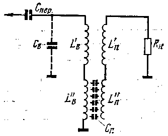
The converted circuit consists of two inductively coupled coils (located on the same frame) and two capacitors. Calculations show that the value of capacitance Sv for all amateur bands is approximately equal to the output capacitance of most generator tubes. The capacitance Sp turns out to be small, which makes it possible to replace it with the capacitance of the coils Lp and Lv. In practice, such a circuit can be made in the form of two inductors located on the same frame and interconnected by inductive and capacitive couplings (Fig. 4). The circuit can be switched on both at the output and at the input of the final stage of the transmitter, if the final stage is made as a separate structure. In the latter case, the power amplifier will have only one tuning element - a range switch. With a rational choice of local oscillator frequencies, such a circuit can also be used in the mixing stages of the transmitter, which eliminates the need for adjustment and pairing of intermediate stages.
The calculation of non-tuning circuits is carried out in the following order 1. Select the loop bandwidth (frequencies f1 and f2). To obtain sufficiently acceptable values of the contour elements, the bandwidth must be at least 5% of the center frequency of the range. 2. For the selected load resistance (wave impedance of the cable), the values of the elements of the original filter are calculated using formulas (1). 3. Find the value of n2 for the selected load resistance and the required resistance of the anode circuit (obtained when calculating the output stage of the transmitter). 4. According to formulas (2), the contour elements and the value of the coupling coefficient K are calculated. 5. Choose a frame and wire diameter. For windings L "in, L" p and L "p with a transmitter power of 100 W, you should choose a wire no thinner than 1 mm. The diameter of the wire for the winding L'v can be taken 1,5-2 times smaller. It is best to use PEV-2 wire, which has a high electrical strength. 6. Calculate the number of turns of the bifilar winding L "in and L" p to obtain the required Sp value. 7. Calculate the number of turns of the windings L'v and L'n (according to the known inductance). 8. According to the known coupling coefficient K, the windings are placed on the frame. Calculations for items 6, 7 and 8 are made according to well-known formulas available in radio engineering reference books. The calculation carried out is indicative, therefore, the contours made according to the calculation must be adjusted in real conditions. The adjustment is made by taking curves of changes in the anode current of the lamp with changes in the frequency of the exciting voltage (Fig. 5).
When taking curves, the circuit must be loaded on a non-inductive resistor with a resistance equal to the characteristic impedance of the cable. Let us assume that the curve initially has the form 1. If we reduce the number of turns of the winding L'n, the curve will take the form 2. If we move the winding L'v (or part of it) up, the curve will take the form 3. Increasing the number of turns of the bifilar winding gives curve 4. Curve 5 corresponds to a correctly tuned contour. The table shows the number of turns of the coils, calculated for an anode load resistance of 3900 ohms, a feeder impedance of 50 ohms and a frame with a diameter of 25 mm.
Author: V. Kustov (UA3FN); Publication: N. Bolshakov, rf.atnn.ru
Machine for thinning flowers in gardens
02.05.2024 Advanced Infrared Microscope
02.05.2024 Air trap for insects
01.05.2024
▪ New AMD FX-series processors ▪ NearLink wireless technology ▪ LMZ10501 - DC/DC nanomodule with load current up to 1 A ▪ A88W 3D FM2+ Hi-Fi Motherboard for AMD Processors
▪ section of the site Electrician in the house. Article selection ▪ article Skryabin Alexander Nikolaevich. Famous aphorisms ▪ article Are there flowers that are fragrant at night? Detailed answer ▪ article Foreman of crop production. Standard instruction on labor protection ▪ article Miniature TV. Encyclopedia of radio electronics and electrical engineering
Home page | Library | Articles | Website map | Site Reviews www.diagram.com.ua | ||||||||||||||||||||||||||||||||||||||||


 Arabic
 Bengali
 Chinese
 English
 French
 German
 Hebrew
 Hindi
Hindi Italian
 Japanese
 Korean
 Malay
Malay Polish
 Portuguese
 Spanish
 Turkish
 Ukrainian
 Vietnamese


 Leave your comment on this article: