TV filter. Encyclopedia of radio electronics and electrical engineering

Encyclopedia of radio electronics and electrical engineering / Knots of amateur radio equipment. Filters and matching devices
 Comments on the article
The number of amateur radio stations is steadily growing every year and the problem of combating interference with television during the operation of an amateur radio station is becoming one of the most pressing. It is especially relevant for beginner radio amateurs and for those who live in settlements located at a considerable distance from transmitting television centers and repeaters, where the television signal is rather weak and therefore more susceptible to interference. Interference in the reception of television programs mainly occurs due to spurious radiation of the transmitter during the nonlinear operation of its cascades, poor shielding or a poorly tuned antenna (SWR> 1), as well as when harmonic components of the main signal enter the television channel band. Sometimes there are nutritional problems.
To effectively suppress harmonic components, low-pass filters (LPF) are often used at the transmitter output. Such a filter should pass frequencies up to 30 MHz without significant attenuation and significantly attenuate signals of higher frequencies. At the same time, its input and output resistances must be matched with the wave impedance of the feeder line. The number of filter sections is chosen depending on the required amount of spurious radiation suppression.
According to the recommendation of the CCIR and the requirements of GOST, the average power of any spurious radiation entering the feeder should be 40 dB lower than the average power of the main signal, but not more than 50 mW [1]. Therefore, a sufficient degree of suppression of spurious radiation in radio stations with an input power of up to 200 W will be completely provided by a five-section filter, the degree of suppression of which is determined by the formula: b=10lg(P1/P2):n where Pi is the output power; P2 - input power; n is the number of filter links. A five-link filter, the scheme of which is shown in Fig. 1, was proposed by S. G. Bunin and L. P. Yailenko [2].

Ris.1
It did not receive proper distribution due to the fact that the authors did not provide the brands of radio components used and data on the dimensions and manufacturing technology of the filter. The proposed technology for manufacturing such a filter is quite simple and does not require much experience and scarce parts, as well as special devices for manufacturing and tuning. It is quite within the power of beginner radio amateurs. Structurally, the filter is made in a box of double-sided foil fiberglass with a thickness of 1,5 mm (the use of fiberglass of a different thickness is undesirable due to changes in the filter's constant capacitances). The height of the box is not critical and in this case is 40 mm. On the main board (Fig. 2), which is the bottom of the box, foil plates are formed by cutting or etching according to the indicated dimensions for a 75-ohm cable (dimensions for a 50-ohm cable are indicated in brackets).
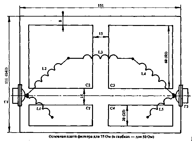
Fig.2 (click to enlarge)
These plates form finely tuned filter capacitors.
Loop coils are made of ordinary copper wire PEV-2 with a diameter of 2,0 mm. The winding is frameless. The inner diameter of the coil is 12,5 mm. Winding pitch - 3 turns / cm (i.e. L-2 cm, etc.). The filter parameters are given in Table. one.
| Characteristic impedance of the cable | C1, C4 pF | C2,. C3 | L1, L5 | L2, L4 | L3 |
| turn. | μg | vyt k. | μg | turn. | μg |
| 50 | 50 | 170 | 3.5 | 0.15 | 8 | 0.32 | 9 | 0.36 |
| 75 | 40 | 120 | 6 | 0.27 | 11 | 0.44 | 13 | 0.66 |
The coils are soldered to the connectors and to the capacitor plates. The place of soldering is not critical. Connectors G1 and G2 - type СР-50, СР-75 and the like. You can use the filter without connectors by including it in the cable break. In this case, instead of a connector, the coil is attached to an insulator and the central core of the cable is soldered to it. The braid, threaded inside the box, is soldered around the perimeter. If the dimensions are correctly maintained, the filter does not require adjustment. It should be noted that the filter does not eliminate interference caused by poor contact between the antenna and the power line. Experimentally, the filter was tested on random antennas fed by a coaxial cable with a significant SWR and a power of more than 200 watts. There was no TV interference. This filter was repeated by more than a hundred radio amateurs. Without tuning, he showed good results.
Literature
1. "Radio", No. 10, 1983, pp. 17-20.
2. S.G. Bunin, L.P. Yaylenko. Handbook of a radio amateur-shortwave. Kyiv: Technique, 1978, p.190.
3. "Amateur Radio", Nos. 5-6, 1976
Author: A. Ronzhin, Vladimir region, Petushki; Publication: N. Bolshakov, rf.atnn.ru
 See other articles Section Knots of amateur radio equipment. Filters and matching devices.
Read and write useful comments on this article.
<< Back
 Latest news of science and technology, new electronics:
Air trap for insects
01.05.2024
Agriculture is one of the key sectors of the economy, and pest control is an integral part of this process. A team of scientists from the Indian Council of Agricultural Research-Central Potato Research Institute (ICAR-CPRI), Shimla, has come up with an innovative solution to this problem - a wind-powered insect air trap. This device addresses the shortcomings of traditional pest control methods by providing real-time insect population data. The trap is powered entirely by wind energy, making it an environmentally friendly solution that requires no power. Its unique design allows monitoring of both harmful and beneficial insects, providing a complete overview of the population in any agricultural area. “By assessing target pests at the right time, we can take necessary measures to control both pests and diseases,” says Kapil ... >>
The threat of space debris to the Earth's magnetic field
01.05.2024
More and more often we hear about an increase in the amount of space debris surrounding our planet. However, it is not only active satellites and spacecraft that contribute to this problem, but also debris from old missions. The growing number of satellites launched by companies like SpaceX creates not only opportunities for the development of the Internet, but also serious threats to space security. Experts are now turning their attention to the potential implications for the Earth's magnetic field. Dr. Jonathan McDowell of the Harvard-Smithsonian Center for Astrophysics emphasizes that companies are rapidly deploying satellite constellations, and the number of satellites could grow to 100 in the next decade. The rapid development of these cosmic armadas of satellites can lead to contamination of the Earth's plasma environment with dangerous debris and a threat to the stability of the magnetosphere. Metal debris from used rockets can disrupt the ionosphere and magnetosphere. Both of these systems play a key role in protecting the atmosphere and maintaining ... >>
Solidification of bulk substances
30.04.2024
There are quite a few mysteries in the world of science, and one of them is the strange behavior of bulk materials. They may behave like a solid but suddenly turn into a flowing liquid. This phenomenon has attracted the attention of many researchers, and we may finally be getting closer to solving this mystery. Imagine sand in an hourglass. It usually flows freely, but in some cases its particles begin to get stuck, turning from a liquid to a solid. This transition has important implications for many areas, from drug production to construction. Researchers from the USA have attempted to describe this phenomenon and come closer to understanding it. In the study, the scientists conducted simulations in the laboratory using data from bags of polystyrene beads. They found that the vibrations within these sets had specific frequencies, meaning that only certain types of vibrations could travel through the material. Received ... >>
| Random news from the Archive Quantum computers for data processing
10.08.2013
Finding patterns in large datasets is a task for which quantum computers can be used for the foreseeable future, says physicist Seth Lloyd.
Automated search for patterns in large data sets is a task that belongs to the field of machine learning. "The advantages (of machine learning methods) are that you can find patterns without (manually) analyzing individual records in a dataset. If, for example, we are talking about identifying patterns in transcripts of human DNA, they can be searched for in such a way that each individual the record, for example, your own, remains safe," Lloyd explained. Now he is developing such a machine learning algorithm for a quantum computer.
"Searching for patterns in data - I think this is a task for which they (quantum computers) will soon be useful," said Seth Lloyd from the Massachusetts Institute of Technology (USA) at the presentation of the Russian translation of his book "Programming the Universe ", held in the framework of the second international conference on quantum technologies.
"(So far, quantum computers have been mainly used) to model and understand how other quantum systems work. We don't understand how quantum systems work very well, but we understand them enough to build a quantum computer that will help us understand them better. This, I think their main use at the present time," explained the physicist.
One of the largest scientific forums in the history of modern Russia, the second international conference on quantum technologies was recently held in Moscow. The conference was organized by the Russian Quantum Center with the support of the Department of Science, Industrial Policy and Entrepreneurship of the city of Moscow and RVC OJSC.
|
Other interesting news:
▪ Why is it difficult to sleep in a new place?
▪ space headache
▪ Corn has a brain
▪ Wind turbine without blades
▪ Obesity Vaccine
News feed of science and technology, new electronics
 Interesting materials of the Free Technical Library:
▪ Modeling section of the site. Selection of articles
▪ Article by Menander. Famous aphorisms
▪ article How clothes were improved? Detailed answer
▪ Tropical Alfalfa article. Legends, cultivation, methods of application
▪ article Hair removers. Simple recipes and tips
▪ article Electrical installations for special purposes. Electrothermal installations. Arc electric furnaces. Encyclopedia of radio electronics and electrical engineering
Leave your comment on this article:
 All languages of this page
Home page | Library | Articles | Website map | Site Reviews

www.diagram.com.ua
2000-2024


 Arabic
 Bengali
 Chinese
 English
 French
 German
 Hebrew
 Hindi
Hindi Italian
 Japanese
 Korean
 Malay
Malay Polish
 Portuguese
 Spanish
 Turkish
 Ukrainian
 Vietnamese