|
|


 Arabic
 Bengali
 Chinese
 English
 French
 German
 Hebrew
 Hindi
Hindi Italian
 Japanese
 Korean
 Malay
Malay Polish
 Portuguese
 Spanish
 Turkish
 Ukrainian
 Vietnamese
|
ENCYCLOPEDIA OF RADIO ELECTRONICS AND ELECTRICAL ENGINEERING Amateur miniature soldering irons. Encyclopedia of radio electronics and electrical engineering
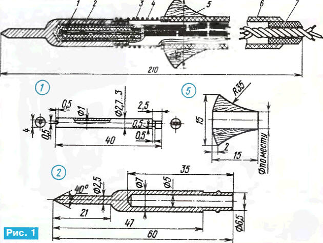
Encyclopedia of radio electronics and electrical engineering / Ham Radio Technologies An easy-to-use soldering iron, suitable for mounting miniature radio components, is still the dream of many radio amateurs today. Let's take a look at how this problem was solved many years ago (Radio, 1978, No. 3, pp. 46-48). One of the possible designs of a homemade soldering iron is shown in Fig. 1. The frame 1 of the heater winding is a ceramic tube. The flat and grooves on the tube are machined with an abrasive bar. Sting 2 is machined from copper on a lathe and nickel-plated to increase resistance to burning.
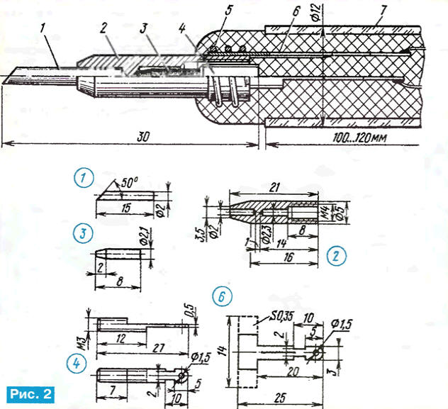
Handle 6 in the form of a thick paper tube is glued on a smooth mandrel with epoxy resin or BF-2 glue. After winding about a third of the wall thickness, the tip holder 20 is glued into the handle for a length of about 3 mm, which is a tube made of tin with a thickness of 0,35 mm. Then wind the rest of the paper. The length of the holder is 50 mm, the outer diameter is 6,5 mm, the gap at the junction should be 1 ... 1,5 mm wide. After drying, the surface of the handle is leveled and a wooden flange 5 is put on the glue, which allows you to put the soldering iron on the table surface without fear of damaging it. When assembling the soldering iron, the tip is inserted into the holder tube and spring 4 is put on top, which tightly covers the tube, fixing the tip. The protrusions on the landing surface of the tip and the reciprocal recesses on the tube prevent the tip from turning around the longitudinal axis. The heater is made as follows. To the frame 1 from the side of the flat, a wire bandage is used to attach a lead twisted from three to four nichrome bare conductors with a diameter of 0,08 ... 0,12 mm. Then a second similar output is made, and its end is rolled into a tight ball of such a size that it does not pass into the frame hole. Lead length - 120...130 mm. To wind a heater rated for a voltage of 36 V at a power of about 10 W, an insulated nichrome wire with a diameter of 0,1 ± 0,02 mm is needed. If the wire does not have a black insulating oxide film, it must be heated with current to a red heat to form such a film. The stripped end of the heater wire is wrapped around the second terminal along its entire length and inserted into the frame hole until the ball stops. The heater wire through the radial groove is brought to the surface of the frame, and the heater is wound tightly coil to coil in one layer. The second end of the winding is stripped to a length of 140 mm and wrapped around the output attached to the flat, starting from the bandage. The cold heater resistance should be approximately 130 ohms. Insulating paste is prepared from 100 parts (by weight) of white sand ground in a mortar, 20 parts of silicate office glue (liquid glass), 2 parts of powdered sugar and 4 parts of a twenty percent solution of caustic soda. One soldering iron requires no more than 4 g of paste. All components are placed in a porcelain mortar and thoroughly ground until a creamy state is obtained. A piece of fiberglass tube is put on the heater, it is melted in a flame from the side opposite to the leads, and it is abundantly impregnated with paste. In the absence of a tube, the heater can be wrapped with a layer of fiberglass and impregnated with paste. The hole in the sting 2 is filled with paste and a heater is inserted there. Excess paste is removed, and the sting is dried for a day at a temperature of 40 ° ... 50 ° C. Then ceramic insulators (in the form of tubes or beads) are put on the leads and connected to the power cord. Before final assembly, the cord is fixed in the handle in one way or another, preventing it from being pulled out. A rubber bushing 7 is glued into the hole of the handle and, finally, a coupling spring 4 is put on. If it is necessary to provide for the grounding of the soldering iron, then a third conductor is added to the cord, the end of which is passed from the inside through the hole in the holder 3 and soldered to it. After the final assembly, the soldering iron is switched on for a voltage equal to half the nominal voltage and heated for two to three hours. The soldering iron can be made for high power. For power, for example, 14 and 18 W, the resistance of the heater should be equal to 92 and 72 ohms, respectively, the tip diameter should be 4 and 6 mm. Authors: L.Medinsky, V.Skorin, Novosibirsk Drawings of a simple soldering iron heating head are shown in fig. 2. The soldering iron must be powered by a step-down transformer with good insulation between the windings, since one of the terminals of the soldering iron power circuit is connected to its body. Soldering iron heater - graphite. Power consumption - approximately 5 W at a supply voltage of 3 ... 4 V.
A soldering iron can be easily made in a home workshop in a few hours, and it will require the simplest materials: a thick nail, a steel screw, a strip of tinplate, a piece of thick copper wire, a glass tube, a fragment of a graphite pencil rod, a steel spring, a little asbestos and silicate glue . The heating element 3 is a piece of a pencil rod with a hardness of TM. A rod 3 ... 5 cm long is heated with current for 1 ... 3 minutes at a bright red heat. A strong layer of brown soot is formed on the surface of the rod, which serves as an insulator. A part of the required length is broken off from the rod and sharpened into a cone, cleaning off carbon deposits. The manufacture of a copper case 2 heads does not require explanation. The outer surface of the housing for a length of 5 mm from the right edge according to the figure is tinned with refractory solder. Conclusion 4 is made from a long M3 screw. The head is sawn off, the remaining part is processed with a file, according to the drawing, the hole is drilled and tinned. Petal 6 is cut out of tinplate with scissors, the wide part is bent into a ring, and the narrow part is slightly bent along for greater rigidity. Sting 1 is made of copper wire with a diameter of 2 mm. It should be firmly inserted into the corresponding hole in the housing 2. Collect the head as follows. A small lump of loose asbestos is impregnated with silicate glue and inserted like a cork into the threaded hole of the body 2. A hole is pierced in the center with a thick needle in the cork and gently expand it, shaking the needle in different directions. Threaded terminal 4 is carefully screwed into this hole. The case with the output is heated with a powerful soldering iron for 1 ... 2 minutes, after which the output 4 is unscrewed, and a strong insulating sleeve made of asbestos with a thread remains in the body (not shown in Fig. 2). To facilitate the unscrewing of the outlet, it should first be lightly lubricated with liquid mineral oil. The channel of the heating element is cleaned of excess asbestos and glue with a drill, the element is inserted into it, the thread on terminal 4 is degreased, lubricated with silicate glue and screwed into place with little effort. The head circuit is checked with an ohmmeter - it should show a resistance of 2 ... 3 ohms. For final drying, the head is connected to the rated operating voltage. The protruding part of terminal 4 is insulated with a layer of asbestos impregnated with glue, and petal 2 is put on body 6. To improve contact, the assembly is additionally fixed with spring 5. Conductors are soldered to the terminals of the head, the terminals are wrapped outside with asbestos impregnated with silicate glue, and tightly inserted into glass tube 7 serving as a soldering iron handle. The inner diameter of the glass tube should not be less than 6 mm, length - 100 ... 150 mm. The choice of a glass tube for the handle is dictated by the fact that it is not in short supply, sufficiently heat-resistant and does not conduct heat well. The described soldering iron has an interesting property - it is protected from severe overheating. With an increase in the body temperature, due to the difference in the coefficients of thermal expansion of copper and graphite materials, the clamping force of the heating element in the body decreases. In this case, the contact resistance increases, the current and, accordingly, the heater power decrease. As the case temperature decreases during the soldering process, the contact is restored and the power increases. Author: V.Ovsyannikov, Tashkent
Artificial leather for touch emulation
15.04.2024 Petgugu Global cat litter
15.04.2024 The attractiveness of caring men
14.04.2024
▪ People with myopia sleep worse than people with normal vision ▪ CIGS solar modules from TSMC Solar
▪ section of the site Application of microcircuits. Article selection ▪ article Influxes and panoramas. video art ▪ article What Do Workers Do With Chopsticks When Hiring for Asian Chipmakers? Detailed answer ▪ Vigna article. Legends, cultivation, methods of application ▪ article Heavy eyelids. Focus Secret
Home page | Library | Articles | Website map | Site Reviews
www.diagram.com.ua |

 Leave your comment on this article: