|
|


 Arabic
 Bengali
 Chinese
 English
 French
 German
 Hebrew
 Hindi
Hindi Italian
 Japanese
 Korean
 Malay
Malay Polish
 Portuguese
 Spanish
 Turkish
 Ukrainian
 Vietnamese
|
ENCYCLOPEDIA OF RADIO ELECTRONICS AND ELECTRICAL ENGINEERING Search for short circuits of conductors of printed circuit boards. Encyclopedia of radio electronics and electrical engineering
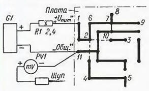
Encyclopedia of radio electronics and electrical engineering / Ham Radio Technologies In the article by I. Nechaev "Search for a short circuit in circuit board conductors" in "Radio", 1996. No. 6. p. 52. 53, a device is described for searching for short circuits in printed circuit boards after their manufacture, which greatly facilitates this work. It is very convenient for small-scale production of various devices. In amateur radio practice, the need to search for short circuits in boards occurs relatively rarely, so the manufacture of such a device, albeit relatively simple, is hardly justified. In some cases, it is more appropriate to use the method described below. It does not require special equipment and is suitable for both "clean" and already mounted boards. Consider the proposed method using the example of searching for a short circuit between the positive and negative power conductors of a digital device. Such a case is most indicative, since these conductors are distributed throughout the board and fit to each microcircuit. A fragment of one of the options for the location of conductors on a conditional board is shown in the figure. Some characteristic points on it are numbered. The location of the emergency circuit is shown by a thin line between points 7 and 10. A voltage-regulated power supply G1 is connected to the board (if it is already mounted, then with polarity observed) in series with a resistor R1, which provides the operating current through the conductors. The value of the operating current is chosen from the condition - the voltage drop between points 1 and 11 should be within 40 ... 100 mV (usually - from 0.5 to 1,5 A, depending on the width of the printed conductors).
To test a "clean" board, a voltage source of up to 5 V is suitable. If, however, it is required to check an already mounted board, then the voltage should in no case exceed the nominal value for the device under test, but it is best to reduce it to 0,5 V (at the same time, p-n junctions of semiconductor devices remain closed). To one of the conductors of the board, for example, to a common wire, the negative output of the digital millivoltmeter PV1 is connected. and its positive output is supplied with a flexible wire with a sharp needle soldered to its end. Now they touch the positive conductor of the board with the tip of the needle, starting from the output "+ Upit". and, moving along it and its branches, they find a point where the voltmeter readings are minimal, and smaller readings can only be obtained by switching to one of the adjacent conductors of the board. Let's turn to the drawing. The voltage at point 1 is maximum, at point 2 it is less due to the voltage drop on the segment 1-2 of the conductor. When moving to points 3 or 4, 5, the voltage will not change - there is no voltage drop in these sections, but at point 6 it will decrease, which means that the search is going in the right direction. At point 7, the voltage will be even less, but at points 8 and 9 it will be the same. as in point 7. therefore, it is she who meets the above requirements. At point 10 of the adjacent conductor, the voltage will either be the same. as in 7. or a little less. Therefore, the closure occurred near points 7 and 10. The described device is designed to work together with a digital voltmeter, since before each measurement it is necessary to remember the exact value of the previous reading for comparison. In extreme cases, you can use any DC microammeter with the largest possible scale. A device with a total arrow deflection current of 50 ... 500 μA is suitable. In series with the microammeter, it is advisable to include a variable quenching resistor, which will allow you to change the upper limit of the measured voltage. When working with mounted boards, you should be very careful in choosing the voltage of the power supply G1 and the resistance of the resistor R1. If the circuit is random and disappears unexpectedly during the search, this should not damage the device. It is advisable to use a source with a current limiter at a level of 2 ... 3 A (many laboratory power supplies have this capability). In the case when the source allows you to adjust the voltage from zero, it is usually possible to set a voltage value at which the connecting wires will play the role of a current-limiting resistor. It should be borne in mind that the microammeter in the event of an accidental disappearance of the circuit may fail due to overload. To avoid this, it is necessary that the first touch to each point of the conductor is short. When the device "goes off scale", the probe must be immediately disconnected. Author: S. Biryukov, Moscow
Artificial leather for touch emulation
15.04.2024 Petgugu Global cat litter
15.04.2024 The attractiveness of caring men
14.04.2024
▪ section of the Antenna website. Article selection ▪ article You must eat in order to live, not live in order to eat. Popular expression ▪ article Why is gold considered a precious metal? Detailed answer
Home page | Library | Articles | Website map | Site Reviews
www.diagram.com.ua |

 Leave your comment on this article: