New schemes of super-regenerative radio receivers for VHF experiments. Encyclopedia of radio electronics and electrical engineering

Encyclopedia of radio electronics and electrical engineering / radio reception
 Comments on the article
The N1TEV article "New Super-Regenerative Circuit for Amateur VHF and UHF Experimentation" describes several circuits for super-regenerative VHF radio receivers. The author describes the history of creation and the principle of operation of such receivers. Their "classical" schemes on lamps and transistors are given.
For example, Figures 1...3 show diagrams of super-regenerators at 144 MHz, made according to traditional circuitry.
Ris.1
Ris.2

Ris.3
Further, the author considers the operation of superregenerators for narrow-band FM and proposes three experimental designs of receivers made by him. The basic circuit of the 144 MHz super-regenerator proposed by him is shown in Fig. 4.
Ris.4
1. Super regenerative receiver for 38-54MHz band.
The circuit contains a high-frequency pre-amplifier on a field-effect transistor Q1, a super-regenerative detector on transistor Q2, and an audio frequency amplifier on a U1 chip of the LM386N type. Transistor Q4 has a voltage regulator for powering high-frequency stages (by adjusting the voltage, it also sets the super-regeneration mode).

Ris.5
Figure 6 shows the design of the coil L2. It contains 7 turns of wire with a diameter of 0.8 mm on a mandrel with a diameter of 6,5 mm. Coil winding length - 25 mm. the withdrawal is made from the middle. The coil is located at a distance of about 18 mm from the "ground". Chokes L1 and L3 - standard 33 µg.
Ris.6
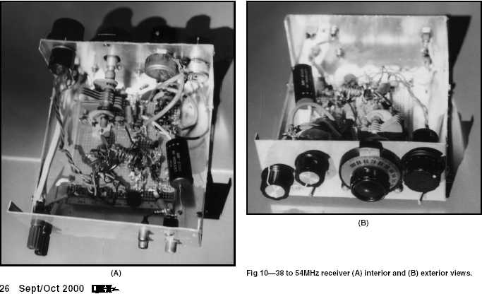
The design of the receiver at 38-54 MHz.
2. Super regenerative receiver for 118-136 MHz (Air-band)
This design is similar to the previous one, but here a noise reduction circuit is added, made on the U2 chip and the Q3 transistor.

Ris.7
In this design, the L2 coil contains 5 turns and is similar in design to the one described above.
3. Super regenerative receiver for 88-180MHz band.
The scheme is similar to the above. The range is divided into two sections 88-150 MHz and 120-180 MHz and is switched by the S1 toggle switch. The bandwidth of the receiver in the range of 15-250 kHz is regulated by resistors R6 (Rqw) and R5B. With R6=0, the bandwidth is maximum.

Ris.8
The design of the coil L2 is shown in Fig. 9. It contains 3,5 turns of wire with a diameter of 0.8 mm on a mandrel with a diameter of 6,5 mm. Coil winding length - 25 mm. the withdrawal is made from the middle. The coil is located at a distance of about 18 mm from the "ground". Chokes L1 and L3 - standard 15 μg.
Ris.9
Structurally, the receivers are surface-mounted on a breadboard with a metallized surface on one side. The connections between the components are made with minimally short jumpers (probably, mounting on "patch" according to Zhutyaev's method is most acceptable here).
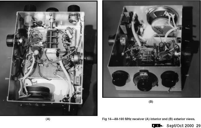
The design of the receiver at 88-180 MHz.
Author: Charles Kitchin, N1TEV, translation and publication: N. Bolshakov, rf.atnn.ru
 See other articles Section radio reception.
Read and write useful comments on this article.
<< Back
 Latest news of science and technology, new electronics:
Artificial leather for touch emulation
15.04.2024
In a modern technology world where distance is becoming increasingly commonplace, maintaining connection and a sense of closeness is important. Recent developments in artificial skin by German scientists from Saarland University represent a new era in virtual interactions. German researchers from Saarland University have developed ultra-thin films that can transmit the sensation of touch over a distance. This cutting-edge technology provides new opportunities for virtual communication, especially for those who find themselves far from their loved ones. The ultra-thin films developed by the researchers, just 50 micrometers thick, can be integrated into textiles and worn like a second skin. These films act as sensors that recognize tactile signals from mom or dad, and as actuators that transmit these movements to the baby. Parents' touch to the fabric activates sensors that react to pressure and deform the ultra-thin film. This ... >>
Petgugu Global cat litter
15.04.2024
Taking care of pets can often be a challenge, especially when it comes to keeping your home clean. A new interesting solution from the Petgugu Global startup has been presented, which will make life easier for cat owners and help them keep their home perfectly clean and tidy. Startup Petgugu Global has unveiled a unique cat toilet that can automatically flush feces, keeping your home clean and fresh. This innovative device is equipped with various smart sensors that monitor your pet's toilet activity and activate to automatically clean after use. The device connects to the sewer system and ensures efficient waste removal without the need for intervention from the owner. Additionally, the toilet has a large flushable storage capacity, making it ideal for multi-cat households. The Petgugu cat litter bowl is designed for use with water-soluble litters and offers a range of additional ... >>
The attractiveness of caring men
14.04.2024
The stereotype that women prefer "bad boys" has long been widespread. However, recent research conducted by British scientists from Monash University offers a new perspective on this issue. They looked at how women responded to men's emotional responsibility and willingness to help others. The study's findings could change our understanding of what makes men attractive to women. A study conducted by scientists from Monash University leads to new findings about men's attractiveness to women. In the experiment, women were shown photographs of men with brief stories about their behavior in various situations, including their reaction to an encounter with a homeless person. Some of the men ignored the homeless man, while others helped him, such as buying him food. A study found that men who showed empathy and kindness were more attractive to women compared to men who showed empathy and kindness. ... >>
| Random news from the Archive MIPI CSI-2 v2.0 specification introduced
14.04.2017
The MIPI Alliance recently released the MIPI CSI-2 v2.0 specification, a new version of the widely used Camera Serial Interface (CSI-2). The new version expands the scope of CSI-2 to the Internet of things, wearable electronics, medical devices, augmented and virtual reality, drones and cars.
Key improvements implemented in MIPI CSI-2 v2.0 include support for RAW-16 and RAW-20 color depth, High Dynamic Range (HDR), and improved signal-to-noise ratio. The number of virtual channels has been increased from 4 to 32, providing enhanced compatibility with image sensors with a variety of data types, support for multiple exposures and other features demanded by driver assistance systems (ADAS). Support for Latency Reduction and Transport Efficiency (LRTE) improves aggregation capabilities without increasing system cost; enables real-time input and processing; optimizes connections, reducing the number of conductors and reducing power consumption.
Support for Differential Pulse Code Modulation (DPCM) 12-10-12 reduces bandwidth requirements while avoiding artifacts. In addition, measures have been taken to improve electromagnetic compatibility and increase the permissible length of connections.
The CSI-2 v2.0 interface can be implemented using one of two physical layer interfaces standardized by the MIPI Alliance: MIPI C-PHYSM or MIPI D-PHYSM.
|
Other interesting news:
▪ Corn that does not require cooking
▪ Noise Buds VS104 Max TWS Silent Headphones
▪ Smart watch with a living organism inside
▪ CC3200+CC2650 Wireless Gateway Connects BLE Sensors to the Internet
▪ Old phone: heat up after use
News feed of science and technology, new electronics
 Interesting materials of the Free Technical Library:
▪ section of the site Application of microcircuits. Article selection
▪ article An ordinary loop becomes springy. Tips for the home master
▪ article In which country did the word selfie originate? Detailed answer
▪ article Head of diving operations. Standard instruction on labor protection
▪ article Project Forget-Me-Not. Encyclopedia of radio electronics and electrical engineering
▪ article Transistors IRF510 - IRF540S. Encyclopedia of radio electronics and electrical engineering
Leave your comment on this article:
 All languages of this page
Home page | Library | Articles | Website map | Site Reviews

www.diagram.com.ua
2000-2024


 Arabic
 Bengali
 Chinese
 English
 French
 German
 Hebrew
 Hindi
Hindi Italian
 Japanese
 Korean
 Malay
Malay Polish
 Portuguese
 Spanish
 Turkish
 Ukrainian
 Vietnamese