|
|


 Arabic
 Bengali
 Chinese
 English
 French
 German
 Hebrew
 Hindi
Hindi Italian
 Japanese
 Korean
 Malay
Malay Polish
 Portuguese
 Spanish
 Turkish
 Ukrainian
 Vietnamese
|
ENCYCLOPEDIA OF RADIO ELECTRONICS AND ELECTRICAL ENGINEERING Project Forget-Me-Not. Encyclopedia of radio electronics and electrical engineering
Encyclopedia of radio electronics and electrical engineering / Security devices and object signaling A micropower radio transmitter, located in a briefcase, backpack, bag, and the owner's miniature radio receiver, which reacts to the disappearance of contact with "radio" things, form a security system capable of detecting the loss at an early stage. Schematic diagram of the microtransmitter "Radio forget-me-nots" is shown in fig. 1. The multivibrator on the elements DD1.1 and DD1.2 generates a meander with a frequency of 0,25 ... 0,3 Hz. The differentiating circuit R3C2 and the element DD1.4 form short pulses with a duration of 20 ms. These pulses control the operation of the high-frequency generator on the transistor VT1.
The transmitter operates in pulsed mode. Only when a high level appears at the DD1.4 output will the conditions for its excitation be created: the electronic key (VT2 transistor) will open in the power circuit, and the necessary initial current will appear in the base of the VT1 transistor. The operating frequency of the transmitter is determined by the installed ZQ1 quartz resonator (26 kHz). The time for the transmitter to enter the operating mode and, accordingly, the front of the radio pulse emitted by it is about 945 ms. The relatively slow entry into the operating mode of quartz oscillators is due to the high quality factor of quartz resonators. In the pause between pulses, the power consumption of the high-frequency part of the transmitter is reduced to almost zero. To reduce it, a resistor R1 is introduced into the power circuit of the DD4 microcircuit, which reduces the voltage across it to a value at which the through currents through the CMOS structures become small. As VT1, any silicon npn transistor with a cutoff frequency of at least 200 MHz can be used. Requirement for VT2: Ukenas <0,2 V. If this transistor has a lower current gain, then to enter it into saturation mode, it will be necessary to reduce the resistance of the resistor R7. Coil L1 - the "magnetic antenna" of the transmitter - is wound coil to coil on a fiberglass plate with dimensions of 20x8 and a thickness of 1,5 mm. The coil contains 30...35 turns wound with PEVSHO 0,25 wire. The ZQ1 quartz resonator must have a frequency approved by Gossvyaznadzor for security systems: 26 kHz or 945 kHz. It is desirable that this be its main resonance. On resonators, the operating frequency of which is the harmonic of the fundamental resonance (often the third), it is usually denoted differently: 26 MHz or 960 MHz. When working with such quartz, the choke-antenna L26,945 will need to be replaced with a full-fledged oscillatory circuit, switched on so that its resistance, given to the VT26,960 collector, does not exceed 1 ... 1 kOhm (shunting with a resistor is possible). The microtransmitter usually works without any external antenna - at "forget-me-not" distances, it is simply not needed. But if necessary, the "range" can be slightly increased. To do this, it is enough to connect a 1-centimeter piece of mounting wire to the collector of the transistor VT10 15. The transmitter can be powered by any 6-volt battery. The dependence of the consumed current Ipotr on the voltage of the power supply Upit is shown in Table. 1. You can use a miniature 6-volt battery type E11A (diameter 10,3 mm, height 16 mm). There is no need for a power switch - just insert the battery into a special socket with spring-loaded contacts. If the transmitter must be in operation all the time, then it is better to solder the battery. Table 1
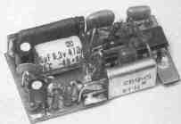
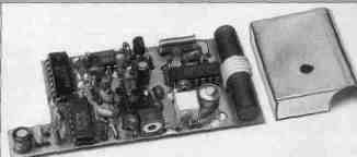
All elements of the microtransmitter are placed on a printed circuit board made of double-sided foil fiberglass 1 mm thick (Fig. 2). The foil on the side of the parts serves as a common wire (the negative terminal of the battery is connected to it). Connections to the foil leads of resistors, capacitors, etc. are shown in black squares, the "grounded" output of the microcircuit is a black square with a bright dot in the center.
The ZQ1 quartz resonator is installed in the cutout of the printed circuit board, and the "grounded" lead is soldered to the foil. Electrolytic capacitors C3 (diameter 4 mm, height 8 mm) and C6 (diameter 8 mm, height 12 mm) are mounted in the "lying" position: C3 - above the microcircuit, C6 - on the board. All resistors are MLT-0,125. Capacitor types: C1 - K10-176, C2 and C6 - KM6, C4 - KD.
The radio receiver "Radionezabudki" is a superheterodyne with a single frequency conversion (Fig. 4). Chip DA1 - a mixer, the input circuit of which is tuned to the frequency of the radio channel of the security alarm 26 945 or 26 960 kHz. The local oscillator frequency is set and stabilized by a ZQ1 quartz resonator. This frequency is offset from the operating frequency of the channel by 465 kHz. The difference (intermediate) frequency signal of 465 kHz, selected by the ZQ2 piezo filter, is fed to the input of the DA2 microcircuit, which includes an intermediate frequency amplifier, an amplitude detector and a low frequency amplifier.
Operational amplifier DA3 is a comparator that converts a low-level pulse signal into a pulse with an amplitude close to Upit. The non-inverting input DA3 monitors the power supply voltage. The signal from the detector is fed to the inverting input DA3 through the integrating circuit R10C15, which significantly reduces the sensitivity of the receiver to impulse noise. In the comparator, the resistor R9 is especially important: the voltage drop across it sets the comparator threshold. So, with the ratings indicated on the diagram, the voltage across the resistor R9 will be 30 mV and the comparator will only respond to input signals whose amplitude exceeds this value. The device that generates an alarm when the microtransmitter disappears, contains a master generator on the elements DD1.1, DD1.2 and a sound generator (DD1.3, DD1.4). The pulse at the input R counter DD2 sets it to zero. A lock has been introduced into the counter: when a high level appears at the CN input, it stops responding to signals arriving at the CP input. In this state, conditions are created for the periodic excitation of the sound generator - it is excited only at a high level at the output 10 DD1.1 and a high level at the output of the counter DD2. Microtransmitter pulses periodically return the counter to the zero state. When the signals of the microtransmitter disappear, the alarm will turn on, and when they resume, they will immediately stop. The magnetic antenna L1 is wound on a ferrite rod MZOVN with a diameter of 8 and a length of 40 mm. You can use a segment of the MZOVN-D9001 magnetic antenna by breaking the core in the right place after a light incision with a diamond file. The winding has 5 turns of MGSHV-0,15 wire laid in a row. The resonant capacitance of the circuit Ср and its quality factor Q little depend on the placement of the coil on the core: Ср=32 pF and Q=260 - if it is located in the middle part of the core, Ср=34 pF and 0=280 - if in 5...6 mm from the edge. The frequency of the quartz resonator ZQ1 is recommended to be chosen below the operating frequency. In this case, the "mirror" reception channel is in a lightly loaded grid B of the civil communication range. Resistor R6, on which the sensitivity of the receiver depends (it grows with the movement of the R6 slider down), can be made both trimmer and variable - with a convenient handle. The screen shown in fig. 4 with a dashed line, is intended not so much to protect the radio from external pickups (its sensitivity is relatively low), but internal ones: signals with steep fronts circulating in DD1 and DD2 have high-frequency components that, if installed unsuccessfully, can affect the receiving path. The screen must not form a short-circuited loop on the magnetic antenna! All fixed resistors in the receiver are MLT-0,125. Capacitor types: C1 -KT4-23; C12, C17 - K50-35 or K50-40; C14 - K53-30; the rest - KD, KM6, K10-176 or similar. Emitter VP-ZP-22.
The receiver is mounted on a printed circuit board made of double-sided foil fiberglass with a thickness of 1,5 mm (Fig. 5). It has three cutouts: to accommodate the supply battery, the ZQ1 quartz resonator and the winding of the magnetic antenna. The assembly is performed in the same way as it is done in a microtransmitter (black squares with a light dot in the center also mark the wire jumpers connecting certain fragments of printed wiring to the "common" foil).
The screen is made of thin brass or tin, its cutting is shown in fig. 6. Three of its sides are bent along the lines shown by the dashed line, and the fourth - by a smooth bend on a 10 ... 11 mm blank. The screen is soldered at the joints, the bottom is leveled and fixed on the printed circuit board by soldering at four points.
In an unmistakably assembled radio receiver, it is only necessary to tune the L1C1C2 input circuit to the frequency of the selected radio channel. This can be done using a standard signal generator and a voltmeter with a scale of 1 ... 2 V. You can send a signal from the generator, for example, by connecting a piece of mounting wire (a kind of antenna) to its output and placing a receiver nearby. The voltmeter must be connected to pin 9 of the DA2 microcircuit. By rotating the rotor of the capacitor C1, they find a position that corresponds to the maximum reading of the voltmeter. The standard signal generator can be replaced by a CB radio station if it has channel 39 in the European standard B grid (this channel corresponds to a frequency of 26 945 kHz) or channel 1 of the Russian standard grid C (26 960 kHz). Tuning the input circuit of the radio receiver can also be carried out directly by the signals of a microtransmitter located 1,5 ... When setting up the receiver using the microtransmitter signals, an oscilloscope is also useful - with its help it is easy to trace the passage of a pulse signal along the receiving path, adjust the input circuit (by the maximum amplitude of the pulses at the inverting input of the op-amp DA2), control the operation of the master and sound generators, etc. The radio receiver is powered by a 6-volt galvanic battery type 476A or an accumulator. In table. 2 shows the dependence of the current Iconsumed by the receiver on the voltage of the power supply Upit. Table 2
Author: R. Balinsky, Kharkov, Ukraine; Publication: N. Bolshakov, rf.atnn.ru
Artificial leather for touch emulation
15.04.2024 Petgugu Global cat litter
15.04.2024 The attractiveness of caring men
14.04.2024
▪ Washing machine LG Tromm ThinQ F21VBV with artificial intelligence ▪ Genes for homosexuality found ▪ Multiple sclerosis depends on the weather
▪ section of the site Dosimeters. Selection of articles ▪ article Pip on the tongue. Popular expression ▪ article Where is the land of flying camels? Detailed answer ▪ article Common Privet. Legends, cultivation, methods of application ▪ article American coaxial cables. Encyclopedia of radio electronics and electrical engineering
Home page | Library | Articles | Website map | Site Reviews
www.diagram.com.ua |

 Leave your comment on this article: