|
|


 Arabic
 Bengali
 Chinese
 English
 French
 German
 Hebrew
 Hindi
Hindi Italian
 Japanese
 Korean
 Malay
Malay Polish
 Portuguese
 Spanish
 Turkish
 Ukrainian
 Vietnamese
|
ENCYCLOPEDIA OF RADIO ELECTRONICS AND ELECTRICAL ENGINEERING TVZ in a tube UMZCH. Encyclopedia of radio electronics and electrical engineering
Encyclopedia of radio electronics and electrical engineering / Tube Power Amplifiers The article gives a brief analysis and determines the realistically achievable parameters of a tube triode single-ended amplifier with a unified TVZ output transformer from a television receiver. The method of alteration of the transformer is considered, which makes it possible to improve its parameters. A practical scheme of the amplifier and test results are given. The approach proposed by the author can be applied in the development of more powerful tube UMZCH. The article is intended for radio amateurs of average qualification, recommendations are limited to information that makes it possible for everyone to repeat the amplifier. Talking about the miracle of tube sound causes a natural desire to hear this miracle. And the first problem that those who want to repeat any tube amplifier will face is the output transformer. It can be solved in three ways. You can make it yourself, it is possible, but not at all easy. You can buy a good output transformer, it's simple, but not cheap at all. And you can try to use something affordable and inexpensive. The study of the radio market showed that the most accessible output transformers (TVZ) from old TVs. The choice is wide, and the price - from 0 3 to 0,6 dollars, depending on the mood of the seller. Most often there are TVZ-1-9, they were purchased for experiments. I also bought other types of transformers for comparison. As it turned out later, the TVZ-1-1 and TV-2A-Sh transformers, the most respectable age, have the best parameters, but there were more TVZ-1 9 on sale, it was with them that I decided to experiment further. The task was set as follows: try to improve the parameters of the transformer by altering it (without rewinding), and then design the output stage in such a way as to compensate its remaining shortcomings as much as possible. It is obvious that the output power of such an amplifier will be relatively small, but the main thing was not to obtain high power, but to search for fundamental solutions. Some theory To figure out where to move, let's remember what parameters of the transformer affect what. If we turn to the classics (for example, [1]), then, without going into subtleties, we can say that six parameters are decisive: the inductance of the primary winding, the amplitude of the magnetic induction, the leakage inductance, self-capacitance, winding resistance and transformation ratio. The parameters of the existing transformers were measured, and this is what happened:
Here are averaged data, unfortunately, only the inscriptions on the coils turned out to be the same for transformers. The material of the magnetic circuit remained unknown, but after taking the magnetization curves, I am inclined to think that this is E44 steel (high-alloy, designed to work in medium high-frequency fields). In principle, what is - that is, but for the calculations it was necessary to have a starting point. Let us estimate what parameters can be expected when using such transformers. Most often they were used in simple amplifiers with output tubes 6F5P, 6FZP, 6P1P, 6P14P in a triode connection. In this case, the output resistance of the lamps is in the range of 1,3 ... 2 kOhm. For calculations, we will take the average value - 1,7 kOhm. On fig. 1 shows a simplified equivalent circuit of a transformer connected to a lamp, which is represented as an oscillator G1 with an output impedance R, (all referred to the primary side of the transformer).
Large Signal Options Let's see how things are with induction in the magnetic circuit. Since the induction is inversely proportional to the frequency, it is the region of low frequencies that is most interesting, where it reaches its maximum values. In fact, the allowable induction will determine the maximum power that a transformer can deliver in the low frequency region with acceptable distortion. The amplitude of induction in the magnetic circuit is determined by the well-known formula
where E1 is the voltage applied to the primary winding, V; f - signal frequency, Hz; S is the active cross-sectional area of the magnetic circuit. cm2; W1 - number of turns. It is convenient to immediately express this dependence in terms of the power in the load. The voltage E1 applied to the primary winding is equal to the sum of the voltages across the load R2' and across the winding resistance r2'. Leakage inductance Ls2' at low frequencies can be neglected. It should be noted that the quiescent current of the lamp I0 flows through the primary winding, creating a magnetizing field, which, in turn, determines the initial value of the induction B0. According to my calculations, it is approximately equal to 0,3T. After transformation, the formula takes the form
For manual calculations, this formula is too cumbersome, but for computer calculations, cumbersomeness does not matter. The dependences of induction on output power calculated for three values of frequency are shown in fig. 2.
If we take into account that the material of the magnetic core begins to saturate at an induction of about 1,15 T (this was found out when taking the main magnetization curve), and assume a maximum induction equal to approximately 0,7 T, then the graphs show what output power can be obtained in the low-frequency region : at a frequency of 30 Hz - only about 0,25, at 50 Hz - about 0,8 W, and at 100 Hz induction is no longer a limiting factor. Exceeding these values not only greatly increases the level of harmonics introduced by the transformer, but also increases the level of harmonics generated by the lamp due to a decrease in the input impedance of the transformer. Measurements in a real cascade (on a 6F5P lamp) showed that at an output power of 1 W, a decrease in the signal frequency from 1 kHz to 50 Hz leads to an increase in the level of harmonics by more than a factor of two. Small Signal Options Let us evaluate the effect of the transformer on the frequency properties of the amplifier when it is operated at low power, when there are no problems with induction (for example, the amplifier is designed for telephones). In this case, it is more convenient to make an assessment using such parameters of the transformer as the inductance of the primary winding and the leakage inductance. From fig. 1 it can be seen that in the low-frequency region the lamp is loaded on two parallel circuits (we neglect leakage inductances). The first is the magnetizing inductance L1, through which the magnetizing current IL1 flows, the second is the load circuit, consisting of resistors R2' and R2' connected in series, through which the current I2 flows. As the frequency of the signal decreases, the reactance L1 falls, respectively, IL1 increases, and I2 decreases. In addition to reducing the transfer coefficient of the cascade, in the general case, one more unpleasant thing is observed - the input impedance of the transformer drops, which leads to a decrease in the resistance of the anode load of the lamp and, accordingly, to an increase in the harmonic coefficient. To assess the influence of the inductance of the primary winding, we use the well-known simplified formula [1]:
where ML is the frequency distortion factor; R0 - equivalent generator resistance, determined from the expression
On fig. Figure 3 shows the results of calculating the frequency distortion of the cascade in the low-frequency region with the output transformer TVZ-1-9 for three values of the output impedance of the lamp.
It can be seen from the graphs that with a lamp output impedance of 1700 ohms (middle curve), a 3 dB drop in frequency response occurs at a frequency of about 40 Hz. Reducing the output resistance of the lamp leads to a decrease in frequency distortion (upper curve). But let's not jump to conclusions and see what happens in the high frequencies. It follows from Fig. 1 that the leakage inductances are connected in series with the load (L1 can be ignored, since the current IL1 is negligible in the region of high frequencies), with increasing frequency, their reactance increases and this leads to a decrease in output power. The coefficient of frequency distortion is determined by the formula
where Mn is the coefficient of frequency distortion; Z - leakage inductance, reduced to the primary winding (measured value). On fig. Figure 4 shows the results of calculating the frequency distortion of a cascade with the same transformer in the high-frequency region for three values of the output impedance of the lamp.
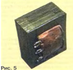
It can be seen that the situation has changed to the opposite - with a decrease in the output resistance of the lamp, the frequency distortion increases. This fact is easily explained: the more the lamp resembles a current source, the less parasitic resistances (including leakage inductance) connected in series with the load affect the output current I1 (I2 = I1 in the high frequency region). This is quite true in the small signal mode. From the foregoing, we can conclude that for an output transformer with not very good parameters, there is some optimal output impedance of the signal source, which makes it possible to obtain the widest possible bandwidth. This resistance is quite easy to calculate by solving an optimization problem in any mathematical package. (If the transformer has a large inductance of the primary winding and small parasitic parameters, this task loses its relevance). This extremely superficial study of the output stage with TVZ transformers answered two questions: what to expect from a standard transformer and what to strive for. As a matter of fact, what to strive for was clear from the very beginning - the parasitic parameters and the amplitude of the induction should be reduced, and the inductance of the primary winding should be increased. But I wanted to quantify the qualitative (rather emotional) definitions "to lower" and "to increase". Unfortunately, such transformer parameters as leakage inductance, transformation ratio and self-capacitance are determined by the design and manufacturing technology of the coil, and without rewinding the latter we cannot change. But not all is lost! By changing the design of the transformer, we can influence the inductance of the primary winding and the amplitude of the induction, and this is not at all small. Alteration of the transformer The only thing that can be done in this case is to change the method of assembling the magnetic circuit. At the factory, it is made with a gap (there is usually no dielectric gasket, the gap is formed due to the loose fit of the packages of W-shaped and closing plates) Let's eliminate the gap by assembling the plates of the magnetic circuit in overlap and let's see what happens. To begin with, the transformer must be freed from the metal clip, after unbending its mounting tabs. Further, having removed the magnetic core from the coil, carefully separate the plates from one another and assemble them again, laying them on top of each other. Do this carefully (to reduce the gap) and be sure to use all the plates. It is possible that there are not enough trailing plates, so it is desirable to have a second transformer with the same magnetic circuit. After assembly, place the magnetic circuit with the wide side on a flat surface (a piece of plywood, getinax, textolite) and with light blows of the mallet on the protruding ends of the plates, ensure that they are flush with the rest. Repeat this operation by turning the magnetic core over to the opposite side. The view of the converted transformer at this stage is shown in Fig. 5. It is advisable to insert the finished transformer into the holder again. The easiest way to do this is using a large bench vise, but especially do not be zealous. Large mechanical stresses degrade the magnetic properties of steel.
The parameters of the converted transformer turned out to be the following: the inductance of the primary winding is 12,3 H, the leakage inductance is 57 mH, the capacitance is 0,3 μF. Comparing them with those given at the beginning of the article, we see that the parameters of the transformer have improved significantly - the inductance of the primary winding has almost doubled, and the parasitic parameters have not changed. You can rightly note that there is now no gap in the magnetic circuit, therefore, there is no linearizing effect of it, and the transformer cannot be used in a traditional cascade with constant magnetization. I agree, but note that after the alteration, the amplitude of the magnetic induction in the magnetic circuit decreased by 0,3 T at the same output power. As a result, the coefficient of harmonics introduced by the transformer has decreased. It is quite obvious that the increased inductance of the primary winding makes it possible to expand the reproducible frequency band in the low-frequency region. Since the converted transformer cannot work with bias, a different type of output stage must be used to excite it. Output stage The most obvious way is to use the so-called choke output stage [2] and separate the transformer from the anode circuit of the lamp with a capacitor (Fig. 6).
This solves the main problem - it eliminates the bias of the output transformer, but requires the use of a choke in the anode circuit. The requirements for it in terms of winding inductance, induction amplitude and parasitic parameters are no less stringent than for the output transformer (I want to immediately warn readers that it is unacceptable to use filter chokes in such a cascade). Therefore, this option is unacceptable for us. The most suitable in this case is the output stage with a current source in the anode circuit [3] (Fig. 7), which has a number of advantages compared to the choke. The high output impedance of the current source makes it possible to obtain maximum gain from the lamp, the cascade has a wider reproducible frequency band, is less demanding on the quality of the power source, and the design as a whole has smaller dimensions.
Let us dwell in more detail on the reproducible frequency band and the quality of the power source. If in the inductor stage we take the inductance of the inductor equal to infinity, and the parasitic parameters are equal to zero, then the stages will have the same gain and bandwidth. But it is impossible to implement such a cascade with a real inductor, since its finite inductance will limit the frequency band from below, and parasitic parameters - from above. But it is quite possible to implement a current source with parameters close to ideal. A great advantage of a cascade with a current source is the absence of strict requirements for the elements of the power source, since the variable component of the load current does not flow through it, it closes in the circuit formed by the lamp, the isolation capacitor and the primary winding of the transformer. This allows you to use any capacitors in the source and not particularly care about reducing the amplitude of the ripples. There are also disadvantages. The most unpleasant thing is that the supply voltage of the cascade with a current source should be much higher (at least one and a half times compared to the choke). The efficiency of the cascade is, accordingly, less, and the circuit is much more complicated. The current source can be made both on a lamp and on transistors. I leaned towards the transistor version for the following reasons. In this case, higher current stability is achievable, the minimum operating voltage is much lower (already a very high anode voltage is needed), no additional filament winding is required for the current source lamp. Particular attention must be paid to the isolation capacitor C1. Its quality affects the output signal, as the output current of the lamp flows through it. It is unacceptable to use oxide capacitors here, only paper and polyethylene terephthalate ones can be used (for example, K73-17 with a rated voltage of at least 400 V; the required capacity is obtained by connecting the required number of capacitors in parallel). Amplifier circuit The circuit diagram of the amplifier is shown in fig. 8, the lamp modes for direct current are also indicated there. The choice of active components was mainly determined by the possibility of their acquisition by a wide range of radio amateurs.
The amplifier is two-stage: the first is made on the triode part of the VL1 lamp, the second (output) - on its pentode part. In both stages, current sources are used in the anode circuit. We discussed the advantages of such a circuit solution in the output stage above, the use of a current source in the pre-amplification stage is also quite justified. Firstly, it allows you to get maximum gain from the lamp. Secondly, its operation at a fixed current makes it possible to reduce the harmonic coefficient of the cascade by two to two and a half times. A good frequency response is ensured by choosing a sufficiently large quiescent current of the lamp. The cascade uses automatic bias, which is formed on the resistor R4, and a shallow local OOS is also introduced through it. If desired, the amplifier can be covered by a common OOS by supplying a part of the signal from the amplifier output through resistor R8 to the triode cathode circuit. The output stage uses a fixed bias, adjustable by the trimmer resistor R12. The main purpose of the resistor R13 is to provide a convenient measurement of the quiescent current of the output stage. Varistor RU1 with qualification voltage 180V (SIOV-S05K180) is used to protect the components of the output stage from overvoltages. Its small parasitic parameters have almost no effect on the output signal. The use of complex cascode current sources is due to the large range of alternating voltage at the lamp anodes [4] (especially in the output stage). The use of simple sources on a single transistor (this also applies to the option on a field-effect transistor with a resistor in the source circuit), recommended by some authors, does not provide acceptable current stabilization in a wide frequency range. In the output stage, even the use of a cascode source does not solve all problems: at frequencies above 25 ... 30 kHz, the gain decay becomes noticeable due to the influence of the capacitances of the VT4 transistor. It is possible to slightly expand the frequency band of the cascade by replacing a pair of transistors VT4, VT5 with one high-frequency high-voltage pn-p transistor of suitable power (for example, 2SB1011). However, such transistors are less accessible. I will touch on one more issue related to the use of current sources and their influence on sound quality. An ideal current source, of course, will not have any effect, but real ones can. Before recommending the current source option under consideration, I studied it in sufficient detail and did not find a significant deterioration in the output signal spectrum in the audio frequency range. The spectrum analyzer HP-3585 from Hewlett-Packard with a dynamic range of 120 dB and a selective voltmeter D2008 from Siemens with an even more impressive value of this parameter - 140 dB were used for research. Of course, there are differences from the resistive stage, but only at the level of -80 ... -90 dB. In many cases, this is already below the stage noise floor. What you really need to pay attention to is the noise level of the cascade with the current source. The use of active elements in the anode circuit leads to a certain increase in noise (this also applies to sources made on lamps), but for cascades operating with input signals of hundreds of millivolts, this is of no fundamental importance. In the input cascades of highly sensitive amplifiers, this should be taken into account. mind. I am not a supporter of the struggle "for the purity of the lamp series" for the sake of the struggle itself and the denial of the real advantages of hybrid devices. The result of this approach, in my opinion, will be trampling around the decisions of the 50s of the last century and reasoning about the necessary composition of the solder used. The most important thing in our case is that the signal is amplified by the lamps (the alternating component practically does not flow through the current source). About some details of the amplifier I will not list specific types of elements that are not indicated in the diagram, but I want to draw attention to some of them. In the cathode circuits of the lamp, it is desirable to use resistors (R4 and R13) with a permissible deviation of resistance from the nominal value of not more than ± 1% (C2-1. C2-29V, etc.), and as trimmers (R5, R12, R14) - multi-turn (suitable for SPZ-37, SPZ-39, SP5-2, SP5-3, SP5-14). Isolating capacitor (C4) - metal-paper (MBGCH, MBGO, MBGT) with a rated voltage of at least 400 V. But, as noted, the use of polyethylene terephthalate (K73-17) with the same voltage is also acceptable. The required capacitance is obtained by connecting the appropriate number of capacitors in parallel. Instead of the SIOV-S05K180 varistor, gas arresters or telecommunication suppressors with a low capacitance for a suitable voltage can be used. Transistor VT4 must be installed on a heat sink capable of dissipating power of 5 ... 6 W (the required cooling surface area is 120 ... 150 cm2). Setting up the amplifier With the use of known good parts and proper installation, there are no problems with adjustment. To set up an amplifier, at least an avometer is needed, it is very desirable to have a 3-hour signal generator and an oscilloscope. Before turning on the amplifier, set the trimmer resistors R5 and R14 to the upper (according to the diagram) position, and R12 to the lower position. This is not a mistake, the VL1.2 lamp must be fully open. The amplifier input must be short-circuited. First, set the quiescent current of the first stage (with resistor R5), then the output (R14). The desired voltage at the anode VL1.2 is achieved last (with resistor R12). Precisely, the bias voltage VL1.2 is selected by applying a signal from the generator to the input of the amplifier (the output, of course, must be loaded with a load equivalent). It is necessary to achieve the maximum swing of the signal voltage at the anode of the output lamp with minimal distortion. It should be noted that the limitation of the upper half-wave of the output voltage occurs quite sharply, which is associated with the exit of the current source from the stabilization mode. When using a lamp current source, this effect is less noticeable. There is an interesting possibility in the output stage. The isolation capacitor C4 and the inductance of the primary winding of the output transformer form a low-quality series oscillatory circuit. With the capacitance C4 indicated in the diagram, its resonant frequency is approximately equal to 10 Hz and does not significantly affect the output signal. By reducing the capacitance of the capacitor, it is possible to shift the resonant frequency of the circuit to higher frequencies, which will lead to a rise (expansion) in the frequency response in the low-frequency region. But this is purely theoretical, the real processes occurring in this circuit are much more complicated, and the result is not always unambiguous. I do not undertake to give recommendations on this matter (it must be evaluated by ear) and I leave the conduct of such an experiment to the discretion of the readers. test data The described amplifier was assembled on a breadboard. Power was supplied from an unstabilized rectifier with an LC filter. Below are the measured parameters of the amplifier and the spectra of the output signal when operating in various modes (general feedback was not used). Load resistance - 4 ohms, supply voltage - 370 V.
The frequency response of the amplifier at two values of the output power is shown in fig. 9. The spectrum of the output signal with a frequency of 1 kHz at an output power of 1,2 W is shown in fig. 10, with a frequency of 30 Hz (at the same output power) in fig. 11 is the same, but with an output power of 0,1 W - in fig. 12 and 13 respectively.
The response of the amplifier to a pulse signal with a frequency of 1 kHz at an output power of 1 2 V is illustrated in Fig. 14. Compared to an amplifier with a traditional output stage and an unmodified transformer, the parameters have clearly improved. If in the region of medium and higher frequencies the changes are small (at a frequency of 1 kHz, the harmonic coefficient decreased by approximately 12%), then in the region of low frequencies the gain is significant. There was a noticeable expansion of the band to the lower frequency region with a significantly lower level of harmonics (almost twice at a frequency of 50 Hz at a power of 1,2 W) With an output power of 0,1 W, the harmonic coefficient at a frequency of 30 Hz does not exceed 1,2% In the spectrum the output signal in all modes is dominated by the second harmonic, the number of higher harmonics is limited and, moreover, their level is very low. The slew rate of the output voltage of the amplifier is low, but there is little that can be done here, large values of the parasitic parameters of the output transformer significantly limit the possibility of correction. The law of "Trishka's caftan" comes into play. An attempt to increase the slew rate leads to a deterioration in other parameters of the amplifier. Conclusion The resulting amp is certainly not an "Ongaku", but it's not a talking $20 can of unknown make either. It has a clear, melodious sound. Of course, a small output power imposes certain restrictions on its use: for scoring a medium-sized room, such power is clearly not enough, but as a telephone amplifier it will not be bad at all. I would compare this amplifier with a bottle of trial perfume. You will be able to evaluate the features of the "tube" sound and decide how much you like it, and not rely on the opinions of other people. The amplifier can be improved. A very promising direction is the use of more "linear" lamps. The simulation results showed that the use of medium power triodes in the output stage makes it possible to reduce the harmonic coefficient at full power by another one and a half to two times. But this inevitably leads to an increase in the number of lamps (which are also scarce) and the complexity of the circuit. The light did not converge like a wedge on TVZ transformers either. Experienced radio amateurs based on the described approach, using transformers of higher quality, can create their own designs with much better parameters. The potential of the output stage with a current source is quite large. In conclusion, I want to note that the use of TVZ type transformers is a big compromise between quality and cost. A high quality tube amplifier must use a good output transformer. Literature
Author: E.Karpov, Odessa, Ukraine
Machine for thinning flowers in gardens
02.05.2024 Advanced Infrared Microscope
02.05.2024 Air trap for insects
01.05.2024
▪ Tunguska meteorite - once in a thousand years ▪ Repetitive routes will reduce the fuel consumption of hybrid cars ▪ Image sensors with 1 µm pixels ▪ Is it easy for a whale to feed ▪ What is healthy for a cat is death for a mosquito
▪ section of the site Dosimeters. Selection of articles ▪ article Beauty is a terrible force! Popular expression ▪ article Blackberry bushy. Legends, cultivation, methods of application ▪ article Simple tachometer. Encyclopedia of radio electronics and electrical engineering ▪ article Manufacture of strip lines. Encyclopedia of radio electronics and electrical engineering
Home page | Library | Articles | Website map | Site Reviews
www.diagram.com.ua |


 Leave your comment on this article: