|
|


 Arabic
 Bengali
 Chinese
 English
 French
 German
 Hebrew
 Hindi
Hindi Italian
 Japanese
 Korean
 Malay
Malay Polish
 Portuguese
 Spanish
 Turkish
 Ukrainian
 Vietnamese
|
ENCYCLOPEDIA OF RADIO ELECTRONICS AND ELECTRICAL ENGINEERING Active filters on field-effect transistors. Encyclopedia of radio electronics and electrical engineering
Encyclopedia of radio electronics and electrical engineering / Audio equipment The article proposes simple active filters based on source repeaters. The low level of distortions and their low order, characteristic of such filters, help to achieve the purity of the sound of spectrally saturated musical signals. This allows them to successfully compete with active filters based on op amps. The advantages of field-effect transistor audio equipment nodes include the low level of harmonic and intermodulation distortions introduced by them into the amplified signals. Due to this circumstance, designers are increasingly using these transistors in the output stages of the UMZCH. However, in preliminary cascades, such devices are rarely used, mainly in amateur developments. And in vain! Their use allows you to create devices that are simple in design without general feedback, creating a warm "tube" sound. The harmonic coefficient of amplifiers, even with local environmental protection, does not exceed 0,1 ... 0,3%, high-order harmonics are practically absent. The advantages of field-effect transistors are especially pronounced in simple designs. True, in this case their main drawback becomes noticeable - a rather large technological spread of their own parameters. As a result, individual adjustment of each product is usually required. This is not an obstacle for radio amateurs, but devices with the simplest circuitry are of little use for mass production. However, this circumstance can also be taken into account: it is enough to use transistors from one batch in small-scale production of a well-functioning design; within the same package, the spread of parameters is not so great. The main condition that was set during the development of the proposed filters is high linearity for signals with levels up to hundreds of millivolts in a wide frequency band with the utmost simplicity of the device. If you use p-channel transistors with a cutoff voltage below -3 V (KPZ0ZG, KPZ0ZE), the required operating mode with a unipolar supply is achieved without gate bias. An isolation capacitor at the input of the cascade is not necessary in this case. And this further improves the sound quality. It is possible to calculate the cascade modes (Fig. 1) for direct current and the transfer coefficient using the linear approximation method [1]. This method is much simpler and clearer than the one given in [2] and provides practically the same results.
For the calculation, it is necessary to know the slope of the characteristics of the transistor S, and it is desirable to use not a reference, but a real value. However, direct measurement of slope in amateur conditions is difficult. Linear approximation makes it possible to use more convenient parameters for measuring the structure: the initial drain current Iini and the cutoff voltage Utr. The slope of the characteristic in this case is determined by the formula: S= Is start/Us. The resistance of the resistor in the source circuit Ri can be roughly selected from the ratio Ri = (3...6)/S. The output voltage of the cascade from the drain VT1 can be approximately determined from the ratio Uout \u1d UBXSRC / (1 + SRi), and the signal voltage at the source - according to the formula Uout \u1d UBXSRi / (3 + SRi), where S is the slope of the transistor; R and RC - resistances in the source and drain circuits (in Fig. 2 - RXNUMX and RXNUMX, respectively). The simplest design is a second-order high-pass filter based on a source follower (Fig. 2). The disadvantages of this filter are related to its low gain. This parameter depends on the steepness of the characteristic and for common low-power field-effect transistors with S = 3...7 mA/V will be 0,8...0,85. Therefore, the calculated (for a unit transmission coefficient) values of the frequency-setting elements have to be corrected or formulas that take into account the actual transmission coefficient [3] should be used for calculation.
So, with the ratings of the parts indicated on the diagram, the calculated cutoff frequency is 72 Hz, and the real one is 85 ... 90 Hz. Although the ratio of ratings R2/R1 - 2 corresponds to the Butterworth filter, the cutoff frequency is slightly higher than the calculated one, and the frequency response inflection is smoother. To increase the steepness of the frequency response in the inflection region, the resistance R1 must be reduced so that the ratio R2/R1 is 3...10. The cutoff frequency can be shifted by proportionally changing the resistance of resistors R1, R2 or the capacitance of capacitors C1, C2. The signal at the output of such a filter is weakened by 2 ... 2,5 dB, while the overload capacity of the cascade is low. Under such conditions, the maximum undistorted output voltage will not exceed 500 mV. To overcome these shortcomings, a combined common-source-common-collector stage (Fig. 3) can be used, but the signal at the output of such a filter will be inverted.
The use of an emitter follower at the output of the filter reduced the output impedance to about 50 ohms and greatly improved the drive capability. With the values of the elements indicated in the diagram, the cutoff frequency is about 80 Hz. The gain (2 ... 3 dB) depends on the characteristics of the applied field effect transistor and the resistance of the resistor R3. Establishment comes down to selecting such a value so that the voltage at the emitter of the transistor VT2 is approximately equal to half the supply voltage. If you have an oscilloscope, it is better to choose the exact resistance value by the symmetry of the output signal limit. Regarding the calculation of the cutoff frequency and filter type, the above considerations are valid. To simulate filters, it is convenient to use the Microcap program. To further increase the slope of the frequency response, you can apply a two-link feedback circuit. On fig. 4 shows a diagram of a trap filter for infra-low frequencies with Fcp = 25 Hz, and in fig. 5 - its frequency response.
On the basis of the considered structure, one can also make a band-pass filter, which is necessary when creating systems with multiband amplification. The scheme of such a filter is shown in fig. 6.
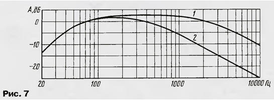
A tunable passive low-pass filter of the first order R5C3 is connected between the cascades. Such a simplification of the filter design became possible because the frequency response of low-frequency dynamic heads in the high-frequency region already has a decline, and in most cases it remains only to match the amplifier bandwidth with it. The frequency response of the filter in the extreme positions of the regulator is shown in fig. 7.
Establishing a filter is similar to the filter options already discussed in the article. It should be borne in mind that the upper limit of bandwidth tuning is determined by the output resistance of the FET stage, and it, in turn, is determined by the resistance of the resistor R4. An example of the combined use of the described filters is shown in fig. 8. This is a block for forming bands of LF and MF-HF of the left and right stereo channels, as well as the total (mono) signal for the subwoofer. The separation of the MF and HF bands is carried out by passive filters at the output of the amplifier. Channel filter circuits are identical to those discussed earlier, so we will focus only on the filter that selects a low-frequency signal for the subwoofer.
The first stage is an adder on two field-effect transistors with a total load R18 similar to that described in [4]. The main filtering is carried out by an active low-pass filter of the second order, made on an emitter follower VT7. The cutoff frequency can be tuned from 40 to 160 Hz with a double variable resistor (R20.1, R20.2). Capacitor C8, together with the output impedance of the first stage, forms a first-order low-pass filter with a cutoff frequency of about 180 Hz. This almost does not affect the course of the frequency response in the passband, but improves the suppression of out-of-band components. Depending on the location of the subwoofer in relation to the left and right channel speakers and the listener, the phase shift of the signals at the listening position can distort the sound image (bass "blurring" or "lag" effect). To correct the phase shift in the subwoofer channel, a regulator with an op-amp DA1 was introduced. A VD1C11 diode-capacitor filter is installed in the power circuit. The following design is specially designed for car audio system. The fact is that a fairly noticeable interior resonance, manifested in a characteristic "buzz" on bass sounds, upsets fastidious audiophiles on wheels. Frequency response measurements show a “hump” of 120 to 160 dB at frequencies of 3 ... 8 Hz! To correct the frequency response in this case, it is convenient to use a notch filter instead of an equalizer. The scheme of such an active filter for one channel is shown in fig. 9 [5].
The first stage is a split load amplifier. Its task is to create anti-phase voltages to power the C2C3R4R5 filter unit. In the right position of the key switch SA1 according to the diagram, an inverted Wien bridge is formed with attenuation of about 3 dB. In the left position of the switch, antiphase voltages are supplied to the filter and the attenuation at the tuning frequency increases to 5...6 dB. The exact attenuation value depends on the transconductance of the transistor and the ratio of the resistances of the resistors R2 and R3. If you make them equal, the attenuation will be maximum (up to 8 dB), but the output signal will be attenuated relative to the input nv 3...4 dB. The diagram shows the optimal variant of the denominations. Since the input impedance of the device is very high, it is better to install the filter near the signal source in order to avoid input interference. The output impedance of the filter is about 50 ohms, which is much less than that of most head units. This will eliminate the influence of the capacitance of the connecting cable, so that the filter simultaneously performs the functions of a matching device. The case must be metal, otherwise you will have to provide it inside with a copper foil shield and connect it to a common wire. The frequency response of the filter (see fig. 9) is shown in fig. ten.
As you can see, this is no longer just a filter, but a real "ambience equalizer". A device with this name and a very similar frequency response is used in the "top" models of Mcintosh amplifiers, only the circuitry is more complicated there ... In addition to the devices indicated on the diagrams, transistors KPZ0ZV-KPZ0ZZh, KT3102 (with any letter index) or other npn structures with h21e> 50 can be used. Any corrected op amp can be used in the phase controller. for unity gain. Oxide capacitors must have an operating voltage of at least 16 V. The choice of other parts is not critical. Literature
Author: A. Shikhatov, Moscow
Machine for thinning flowers in gardens
02.05.2024 Advanced Infrared Microscope
02.05.2024 Air trap for insects
01.05.2024
▪ New three-phase power quality analyzer ▪ Compact charger for BMW electric vehicles ▪ Electronic system for simultaneous interpretation into the sign language of the deaf and dumb
▪ section of the site Wonders of nature. Article selection ▪ article Things for tomorrow! Popular expression ▪ article What is calfskin used for in the English Parliament? Detailed answer ▪ article Operator of a rotary excavator. Standard instruction on labor protection
Home page | Library | Articles | Website map | Site Reviews
www.diagram.com.ua |


 Leave your comment on this article: