
|
|
ENCYCLOPEDIA OF RADIO ELECTRONICS AND ELECTRICAL ENGINEERING Features of the establishment of mixers. Encyclopedia of radio electronics and electrical engineering
Encyclopedia of radio electronics and electrical engineering / Knots of amateur radio equipment. Mixers, frequency converters Due to their simplicity, high sensitivity and selectivity, good reliability, direct conversion receivers and transceivers are popular with radio amateurs. But not always in the apparatus, even made according to a well-established scheme, the capabilities and parameters inherent in it are realized from the very beginning. As a result of many years of operation by the author of this article of this group of communication equipment, it turned out that low-frequency nodes (mainly bass amplifiers) remain operational when the supply voltage drops to 2 ... 6 V (at a nominal value of 9 ... 12 V). At the same time, their gain, as a rule, decreases. The main reason for the unsatisfactory operation of direct conversion receivers and transceivers is the non-optimal operation of the mixer. High parameters are achieved only with careful selection of the heterodyne high-frequency voltage across the mixer diodes. It should be within 0,6 ... 0,75 V on silicon diodes and 0,15 ... 0,25 - on germanium. At lower local oscillator voltages, the mixer gain decreases. It also decreases at high voltages, since the diodes are open almost all the time. This increases the noise of the mixer. The stability of the frequency and amplitude of the voltage supplied to the mixer from the local oscillator (especially on the HF amateur bands) largely depends on the stability of the supply voltage. In almost all the circuits given in the literature, there is no circuit for adjusting the heterodyne voltage on the mixer diodes. It is recommended to select a local oscillator coupling capacitor with a mixer or change the number of turns of the coupling coil. But this process is very time-consuming and, moreover, does not give confidence that the device has been set up properly. The disadvantage of this method is also that in the process of establishing it is necessary to turn off the receiver (transceiver) and solder the capacitor or rewind the coil. But during this time, the amateur station, the reception volume of which is being tuned, often stops working, and therefore it is impossible to know whether the sensitivity of the device being adjusted is increasing or decreasing. It is more expedient to carry out tuning according to the signals of a "weak" station during a stable passage of radio waves, i.e. when there are no noticeable fluctuations in the level of the received signal. Due to the lack of necessary measuring instruments, direct conversion receivers and transceivers are often tuned "by ear", which is not the best way for their parameters.
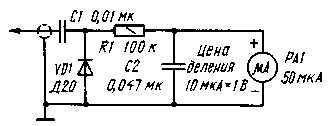
On fig. 1 shows a diagram of a voltmeter-probe, modified in accordance with the recommendations given in [2]. It allows you to quite accurately measure the local oscillator voltage directly on the mixer diodes. Consider simple ways to tune and refine direct conversion receivers and transceivers that allow you to eliminate the above design flaws.
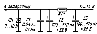
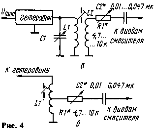
First of all, when finalizing, it is necessary to introduce a circuit for stabilizing the supply voltage of the local oscillator. The stabilizer circuit is shown in fig. 2. Zener diode VD1 is selected with a stabilization voltage 1,5 ... 2 times less than the nominal supply voltage of the receiver (transceiver). Resistor R1 sets the optimal current through the zener diode. The resistance of the resistor R1 must be such that the stabilization current of the zener diode VD1 does not exceed the maximum allowable value. Capacitor C1 reduces the “leakage” of zener diode noise, resulting in reduced noise modulation of the local oscillator voltage, and reduced overall receiver noise. It is convenient to change the RF voltage on the mixer diodes with a tuning non-inductive resistor connected in parallel or in series with the coupling coil (R1, respectively, in Figs. 3 and 4).
In the latter case, you can use both transformer (Fig. 4, a) connection of the local oscillator with the mixer, and autotransformer (Fig. 4,6). With a more precise adjustment of the local oscillator voltage (for example, when receiving signals from hard-to-hear stations "by ear"), the RF voltmeter is turned off.
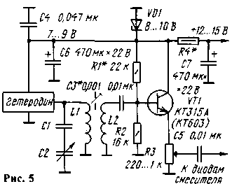
It should be noted that if the above improvements are applied, the number of turns of the coupling coils should be slightly increased, since the introduction of a tuning resistor reduces the output voltage of the local oscillator. This is especially true for the variant, the scheme of which is shown in Fig. 3. Together, the number of turns of the coupling coil, the resistance of the resistor R1 and the capacitance of the capacitor C2 must be such that the voltage on the silicon diodes of the mixer can be adjusted from 0 to 1,2 ... 2 V, on germanium - from 0 to 0,5 ... 1 V. In this case, the optimal voltage is achieved approximately at the middle position of the resistor R1 slider. It is possible to regulate the output voltage of the local oscillator by changing the supply voltage, as, for example, was done in [3]. However, this is only suitable at frequencies up to 3...4 MHz. At higher frequencies (above 7 MHz), such an adjustment can lead to a significant shift in the local oscillator frequency. On fig. 5 shows a diagram of a local oscillator with a buffer node, in which an output voltage regulation circuit is introduced. When repeating, it should be taken into account that the emitter follower does not provide voltage gain, and therefore the high-frequency voltage on the coupling coil must be twice as high. than required for normal operation of the mixer.
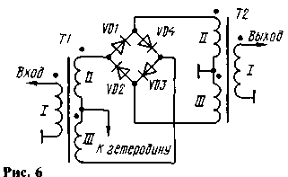
In amateur radio practice, diode balanced mixers are most widely used. Their main advantages are the simplicity of design and configuration, the absence of high-frequency switching when switching from reception to transmission. Balanced mixers on field-effect and bipolar transistors are used much less frequently. In simple balanced diode mixers, the local oscillator voltage and some output conversion by-products can be suppressed by 35 dB or more. But such results are achieved only in one direction: in that in which the mixer is balanced. In the author's design of the transceiver [4], the mixer is balanced only towards the power amplifier. If a double balanced mixer [5] is used, noise will decrease, sensitivity will increase, and noise immunity will improve. Dual balanced mixers are balanced on both inputs (outputs). They suppress not only local oscillator oscillations, but also the converted signal, leaving only the products of their mixing and thus ensuring the purity of the spectrum. The use of such mixers makes it possible to reduce the requirements for the clean-up filter included at the mixer output, and even to abandon it altogether by connecting the mixer output directly to the IF amplifier, at the output of which there should be a main selection filter (for example, an EMF or a quartz filter). A significantly higher signal level can be applied to a double mixer during reception, since it sharply weakens the effect of direct signal or interference detection, i.e. there is no detection without the participation of local oscillator oscillations, as is the case in a conventional amplitude detector. Most often in amateur radio designs, a double balanced mixer is used, the diagram of which is shown in Fig. 6. It is also called ring, since the diodes in it are included but in the ring.
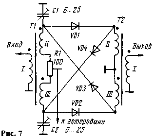
It is often recommended to supplement this mixer with balancing elements R1, C1, C2 (Fig. 7). Moreover, the resistor R1 must be non-inductive. This refinement improves the parameters of the mixer.
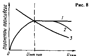
When working on low-frequency ranges, high-frequency transformers are wound, as a rule, on ferrite rings of size K7x4x2 with a magnetic permeability of 600 ... 1000 with three twisted (3-4 twists per 1 cm of length) PELSHO 0,2 wires. Approximately about 25 turns are made (until the ring is completely filled). When installing a transformer, its windings are phased according to Fig. 6 and 7. There are two main options for incorporating a dual balanced mixer into a transceiver. In the first one, the signal passes both during reception and transmission in one direction from the input to the output of the mixers. So, for example, it was done in the well-known transceivers "Radio-76" [6] and "Radio-76M2" [7]. Numerous experiments carried out by the author revealed that when the heterodyne voltage is less than the optimum, the sensitivity in the receive mode deteriorates significantly, and when the voltage is higher, the carrier suppression in the transmit mode is significantly reduced (the sensitivity also drops, but this is less noticeable to the ear than in previous case). The qualitative dependence of the main parameters of the transceivers on the voltage level of the local oscillator supplied to the mixer is shown in fig. 8 (curve 1 - sensitivity during reception, determined by ear, 2 - sensitivity measured by devices, 3 - carrier suppression during transmission).
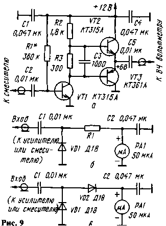
In the second variant, the signal in the receive mode is fed to the input of the balanced mixer, and in the transmission mode - to the output. With this inclusion, the principle of reversibility of the mixer is used. This is how the RF path of the transceiver described in [8] is built. Setting up the mixer in this case also comes down to setting the optimal heterodyne voltage and carefully balancing it. It should be especially noted that the adjustment operation does not depend on the principle of constructing the RF path of the transceiver. Now a few practical recommendations for establishing the RF path of the transceiver. First of all, you need to set up the mixers. Previously, the engines of the balancing resistors in them are set to the middle position. Next, the GSS is connected to the antenna jack of the transceiver and the heterodyne voltage on the mixers is gradually increased. The signal from the GSS is supplied with a level exceeding the sensitivity of the receiving path by several times. It is necessary to achieve signal reception. If there is no generator, the operation is performed by ear, receiving a signal from an amateur radio SSB radio station or a noise generator on a low-power zener diode. Then alternately adjust each of the mixers. First, the optimal heterodyne voltage is selected. To do this, it is gradually increased and evaluated by ear: whether the volume of the reception of the GSS signal, the radio station or the noise generator is increasing. As noted by the author, as the heterodyne voltage applied to the mixer increases, the aural reception volume first increases, reaches a maximum, and then practically does not change (Fig. 8, curve 1). The heterodyne voltage should be set in such a way that when it is slightly reduced, the reception volume drops, and when it is slightly increased, it does not increase. In practice, this is realized by moving within a small range of the resistor engine that controls the level of the output voltage of the local oscillator. If there is no such possibility in the transceiver, then the device should be modified. As a rule, an emitter follower is switched on at the output of one or another local oscillator. In this case, the refinement turns out to be very simple: the constant resistor in the emitter circuit of the transistor is replaced with a non-inductive tuning resistor of the same rating as the constant one. After optimizing the heterodyne voltage, the mixers need to be more carefully balanced again. An RF millivoltmeter or an oscilloscope is connected to the input or output (depending on the design of the transceiver), and by moving the slider of the resistor R1, and then adjusting the capacitors C1 and C2 (see Fig. 7), a minimum of readings is achieved. If devices with high input impedance are used, then resistors close in resistance (within 50 ... 100 Ohms) should be connected to the input and output of the mixer. Preference should be given to balancing towards the output of the transmitting path. The difference in balance between the input and output of the mixer should be small (a few decibels). If it reaches 10 dB or more, then this, as a rule, is a consequence of the fact that the heterodyne voltage applied to the mixer is much higher than the optimal one. To check and balance mixers, the author created simple devices. On fig. 9, a shows a circuit of an RF amplifier, to the input of which a mixer is connected, and a high-frequency voltmeter is connected to the output for coarse tuning (Fig. 9, b), for fine tuning - an RF probe (Fig. 9, c). At the same time, it is not necessary to install additional resistors with a resistance of 50 ... 100 Ohm in the mixer.
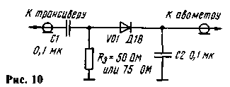
Finally, the mixers are configured after they are installed in the transceiver (it is put into transmission mode). The device must first be set to receive mode. To prevent microphone noise from interfering with balancing, the input of the microphone amplifier is short-circuited. The lowest-frequency mixer is balanced first, and then the rest in order of the signal passing through them in the transmission mode, achieving a minimum of RF readings on a load dummy (Fig. 10) connected to the transceiver power amplifier. After that, adjust the settings of the remaining nodes. It is advisable to repeat this procedure two or three times.
Literature 1. Polyakov V.T. Radio amateurs about the direct conversion technique. - M.: Patriot, 1990, p. 264.
Author: Vladislav Artemenko (UT5UDJ) Kyiv. Ukraine, KV journal 4,5-97; Publication: N. Bolshakov, rf.atnn.ru
Energy from space for Starship
08.05.2024 New method for creating powerful batteries
08.05.2024 Alcohol content of warm beer
07.05.2024
▪ AUO to release 4,3-inch AMOLED panels ▪ New image recognition processors from Toshiba
▪ site section Power supplies. Article selection ▪ article Conventional signs and design of maps. Fundamentals of safe life ▪ article What is an artesian well? Detailed answer ▪ article Three-leaf watch. Legends, cultivation, methods of application ▪ article Foil radiators. Encyclopedia of radio electronics and electrical engineering ▪ article Twilight switch. Encyclopedia of radio electronics and electrical engineering
Home page | Library | Articles | Website map | Site Reviews www.diagram.com.ua |


 Arabic
 Bengali
 Chinese
 English
 French
 German
 Hebrew
 Hindi
Hindi Italian
 Japanese
 Korean
 Malay
Malay Polish
 Portuguese
 Spanish
 Turkish
 Ukrainian
 Vietnamese

 Leave your comment on this article: