|
|


 Arabic
 Bengali
 Chinese
 English
 French
 German
 Hebrew
 Hindi
Hindi Italian
 Japanese
 Korean
 Malay
Malay Polish
 Portuguese
 Spanish
 Turkish
 Ukrainian
 Vietnamese
|
ENCYCLOPEDIA OF RADIO ELECTRONICS AND ELECTRICAL ENGINEERING Network flash. Encyclopedia of radio electronics and electrical engineering
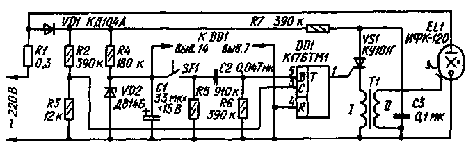
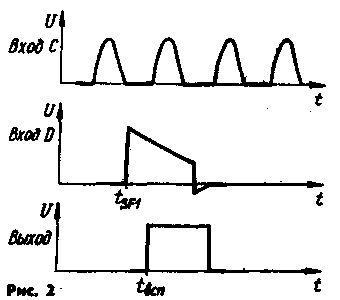
Encyclopedia of radio electronics and electrical engineering / Lighting Network flash lamps for photography come in two types - with and without a storage capacitor. The most widespread are pulsed light sources with a storage capacitor, as they provide reliable operation and constancy of flash energy. At the same time, light sources without a storage capacitor have a much smaller required time interval between flashes (determined mainly by the scattering power of a flash lamp), dimensions and weight, and often cost. Therefore, flash units without a storage capacitor are of constant interest to amateur photographers. Several variants of a network flash without a storage capacitor were described in the Radio magazine [1]. The flash on the thyristor V. Chetverika cannot ensure the constancy of the flash energy and the reliability of its operation, for the reason that the moment of the flash does not always coincide with the maximum voltage of the positive half-cycle of the network at the outputs of the flash lamp. Ignition of a flash lamp will not occur at all if the camera's sync contacts are closed at the moment when the mains voltage passes through "zero" or during the negative half-wave of the mains voltage at the outputs of the flash lamp. There will be no flash even if the mains voltage has not reached the ignition threshold of the flash lamp by the time the camera's sync contacts are closed. The light source on thyratrons by B. Svoisky does not have the noted shortcomings, but it is built on the old element base - thyratrons, a neon lamp - and has rather large dimensions. A clear operation of a pulsed light source without a storage capacitor and the constancy of the flash energy can be easily ensured by introducing into it a node that synchronizes the moment of ignition of the flash lamp with the maximum value of the positive half-wave of the mains voltage at its terminals, even with an arbitrary closure of the synchro-contacts. Such a node can be a single vibrator consisting of a differentiating circuit and a D-trigger [2]. On fig. 1 shows a circuit diagram of a network flash without a storage capacitor, built on the basis of a synchronized single vibrator. When the sync contacts SF1 are closed (they are located inside the camera, but for the convenience of reviewing the operation of the device they are shown here), the capacitor C2 is charged. After opening the sync contacts, the capacitor C2 is discharged through resistors R5 and R6 and a starting pulse is formed at the information input of the D-flip-flop. From the voltage divider R2R3 to the input C of the trigger, clock pulses are received, which are positive half-waves of a sinusoidal mains voltage with an amplitude of about 9 V and a frequency of 50 Hz (Fig. 2). As a result, the flip-flop switches either immediately if the trigger pulse coincides with the clock, or delayed by the period of the clock pulses.
The output pulse from the trigger goes to the control electrode of the trinistor VS1. Capacitor C1 is discharged through the opened SCR and the primary winding of the pulse transformer T3. A high-voltage voltage pulse occurs in the secondary step-up winding of the transformer, leading to ionization of the gas inside the bulb of the flash lamp EL1, which causes it to flash. Resistor R1 limits the current through flash lamp EL1.
For the manufacture of a flashlight, it is convenient to use a factory-made set No. 1 of spare parts for flashlights "Luch-70" (it is used from a housing, a flash lamp with a reflector and a cord for connecting to the camera's sync contacts). All parts of the device, including a flash lamp with a reflector, are mounted on a printed circuit board. The board is attached to the reflector at the back. All parts are placed along the edges of the board. Resistor R1 is made of nichrome wire with a diameter of 0,5 mm, wound on a resistor VS-0,5 of any resistance, the number of turns is 15-20. The pulse transformer T1 is wound on a K 10X6X3 ring magnetic circuit made of 3000NM ferrite. Winding I contains 3 turns of PEV-2 0,31 wire, and winding II - 600 turns of PELSHO 0,1 wire. Care should be taken to ensure reliable insulation between the windings. When unsoldering the cable connecting the flash lamp to the camera, it is necessary that the external output of the sync connector be connected to the right contact of the SF1 pair according to the diagram. A properly assembled flash does not require adjustment. In the flash lamp, which is described in the article by V. Kalashnik, the sync contacts SF1 are under mains voltage. The output of a pair of sync contacts, left according to the scheme, is especially dangerous, since the damaging current from it is practically unlimited (the current from the right output is limited by the large resistance of resistor R5). That is why such a flash can only be used in cameras in which the sync contacts are not electrically connected to the body. At the same time, the editors recommend, in order to increase electrical safety, to supplement the flash with a device that allows you to plug the mains plug into a socket so that the lower mains wire according to the diagram is at zero voltage relative to the ground. This device - a pointer to the phase wire of the network - consisting of a resistor and a neon lamp connected in series, must be mounted in the mains plug of the lamp. The body of the fork can be a plastic jar with a cream lid. Pins are attached to the bottom of it, and a neon lamp is installed from the side of the lid. The free terminal of the resistor (MLT-0,125-300 kOhm) is soldered to the upper network terminal of the flash lamp, and the free terminal of the lamp (TN-0,2) is soldered to a ring of copper or brass foil glued to the outer surface of the plug body. When the lamp is connected to the mains, the plug is taken in the hand so that the fingers touch the ring, and inserted into the socket. If the neon lamp lights up, the inclusion is considered correct, if not, the plug must be removed, rotated 180 ° and re-inserted into the socket - the lamp should light up. In this position of the fork, working with a flash lamp is the safest. Only now can the plug of the connecting cable be inserted into the camera's sync socket. In conclusion, we note that the above measures by no means exempt from the implementation of all precautionary rules when handling electrical installations. At the same time, we invite our readers to think and propose options for a network flash for publication in the magazine, which has all the useful qualities described here, but with a complete "decoupling" from the network of both outputs of sync contacts. Literature
Author: V. Kalashnik, Georgiou-Dezh, Voronezh region; Publication: N. Bolshakov, rf.atnn.ru
Air trap for insects
01.05.2024 The threat of space debris to the Earth's magnetic field
01.05.2024 Solidification of bulk substances
30.04.2024
▪ Space weather threatens self-driving cars ▪ Ultra-fast eMMC Pro Class 1500 memory modules from Samsung
▪ section of the site Children's scientific laboratory. Article selection ▪ article Fundamentals of life safety. Crib ▪ article When was the capital of a European state outside of Europe? Detailed answer ▪ article Promoter. Job description ▪ article Mordant to imitate walnut wood. Simple recipes and tips
Home page | Library | Articles | Website map | Site Reviews
www.diagram.com.ua |

 Leave your comment on this article: