|
|


 Arabic
 Bengali
 Chinese
 English
 French
 German
 Hebrew
 Hindi
Hindi Italian
 Japanese
 Korean
 Malay
Malay Polish
 Portuguese
 Spanish
 Turkish
 Ukrainian
 Vietnamese
|
ENCYCLOPEDIA OF RADIO ELECTRONICS AND ELECTRICAL ENGINEERING Discrete proportional control. Encyclopedia of radio electronics and electrical engineering
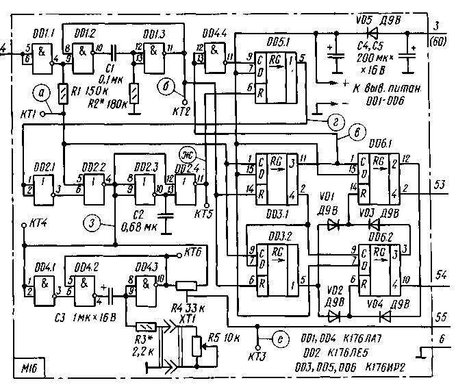
Encyclopedia of radio electronics and electrical engineering / Radio control equipment WHAT IS DISCRETE PROPORTIONAL CONTROL? First, very briefly about the proportional command. If the position of any actuator on the model, such as the steering wheel of a boat, changes according to the law of changing the position of the transmitter control lever, then the model is said to be executing a proportional operator command. Most often, and this is natural, the dependence of the position of the actuator on the position of the control body is made linear (directly proportional). In proportional equipment, as a rule, pulse-width modulation (PWM) is used. The width of the modulating command pulses in the transmitter changes when the position of the control lever changes. The demodulator of the model generates a signal that moves the working body of the actuator in accordance with the width of the modulating pulses of the received PWM signal. In some cases, it is advantageous (in terms of simplicity and cost of radio control equipment) to use discrete proportional control to control a specific model. So, for example, only discrete commands are enough to turn on, turn off and reverse (change the direction of rotation of the rotor) the electric motors of the model, and a proportional command is needed to control the steering mechanism. The movement of such a model is much more natural, it is more maneuverable, it is much easier and more pleasant to control it. The encoder of the discrete-proportional control system is designed in such a way that it is able to form both discrete and proportional commands simultaneously. About such an encoder and will go further story. DISCRETE PROPORTIONAL CONTROL MODULE Its scheme is shown in Fig. 1. Suppose that when the supply voltage is turned on, the variable resistor R3 slider and the movable contact of the SA1 switch are in the middle position. A high level appears at the inverting output (pin 2) of the DD3 trigger (Fig. 2, c), which will allow the passage to the base of the transistor VT1 only of the pulse applied to the combined top two according to the input circuit of the element DD4.2.
After some time, the pulses of the clock generator (it is assembled on the elements DD1.1 and DD1.2) will begin to arrive at the input of the eight-bit shift register DD2.1, DD2.2 and the upper input of the element DD4.2. Level 1 will alternately appear at the register outputs. A high level from output 3 of the DD2.1 register (Fig. 2, b) will start the one-shot assembled on the elements DD1.3, DD1.4, a positive pulse will appear at the output of the inverter DD4.3, which reaches the base of the transistor VT1 (Fig. 2.e). The duration of this pulse depends on the position of the slider of the variable resistor R3. This part of the output signal will be the proportional command.
As soon as a high level occurs at output 4 of register DD2.2, both registers will return to their original state and at the direct output of trigger DD3 the level will change from 0 to 1 (Fig. 2d). This means that the DD4.1 element is ready to skip clock pulses to the output. Five impulses will pass to the output - from the 11th to the 15th "Stop" command (Fig. 2, e). From the 16th clock pulse, the entire considered process for the formation of a proportional pulse and the signals of the "Stop" command will be repeated again. If, during the operation of the encoder, the operator begins to change the position of the variable resistor R3 slider, then the duration of the proportional pulse will change. When moving the slider of the resistor R3 to the right according to the scheme, the duration will increase. With the extreme right position of the engine, the duration of the single vibrator signal is 10 ms, with the average - 6 ms, and with the extreme left - 2 ms. Resistor R2 limits the minimum pulse duration. When you change the pulse width of a one-shot, the slope of the pulse moves, not its front. In position 1 of switch SA1 in each group there will be four clock pulses, which corresponds to the "Forward" command, in position 3 in the group there will be three pulses - the "Back" command. MPN-1 was used as the SA1 switch in the encoder; any other small-sized one for three positions and one direction is also suitable. Variable resistor RZ-SPO-0,5 group A. To establish the module, the oscilloscope is connected to KT1, the module supply voltage is turned on and the selection of resistor R2 (the variable resistor R3 slider must be in the left position according to the diagram) achieves a proportional pulse duration of 2 ms. Move the slider of the resistor R3 to the right position and check the maximum pulse duration. After that, make sure that the number of pulses in the group is consistent in all three positions of the switch SA1. DISCRETE-PROPORTIONAL DECODER MODULE Of course, the constant "hunting" of the desired course of the yacht, which is inevitable with discrete steering, as described in the previous section, is very tiring for the operator. Therefore, the desire to control the steering wheel proportionally is quite natural, and discrete commands are sufficient to control the forward and backward motion. Such an encoder - M4 - has already been considered by us, and now we will talk about the decoder for it. On fig. 3 shows its schematic diagram. Let's consider the process of command decoding using the example of the "Stop" command and a proportional steering impulse.
In the initial state (in the absence of input pulses) all outputs of the registers DD3.1, DD3.2, DD5.1, DD6.1, DD6.2 will be level 0, which corresponds to the "Stop" command. Since the position of the steering wheel of the model corresponds to the position of the slider of the resistor R5 (the resistor slider is mechanically connected to the steering machine), let's assume that they are in the middle position - "Steering wheel straight". Here, the first proportional pulse appeared at the output of the inverter DD1.1 (Fig. 4, a). It will start the single vibrator, assembled on the elements DD1.2, DD1.3, and will go to the counting input C of the registers DD3.1, DD3.2, as well as to the upper input of the DD2.2 element according to the scheme. Since at this moment level 1 will be at the second input of this element, the impulse will not pass through the element. At the end of the pulse, level 1 will appear at output 1 of register DD3.1. After a time of 5T (Fig. 4, b) at the output of the single vibrator (the output of the element DD1.3) level 1 will appear, and the register DD3.1 will be set to its original state.
Then, at the output of the inverter DD1.1, the signals of the "Stop" command will appear, the first of which will again start the one-shot DD1.2, DD1.3. Command pulses will cause the alternate appearance of level 1 at the outputs of registers DD3.1, DD3.2. Level 1 from output 3 of register DD3.1 (Fig. 4, c) will cause a high level to appear at output 1 of registers DD5.1, DD6.1, thereby giving permission for the channel pulse to pass through element DD2.2. After a time of 5T along the edge of the signal of the first single vibrator (Fig. 4, b), the registers DD3.1, DD3.2 will be set to their original state. The positive proportional pulse that appeared at the output of the DD2.2 element will launch this time the second one-shot, assembled on the elements DD4.2 and DD4.3. The duration of its pulse depends on the capacitance of the capacitor C3 and the resistance of the resistors R3, R5. If we assume that the pulse of this single vibrator is exactly equal in duration to the input proportional pulse, then anti-phase, but identical in amplitude and duration, pulses will act on the extreme terminals of the resistor R4 (Fig. 4, e, f). Therefore, at the output - at terminal 55 of the module - a constant voltage will appear equal to half the supply voltage, i.e. there is no mismatch signal. If the durations are different, a mismatch signal of one or another polarity will appear at pin 55, depending on whether the input proportional pulse is longer or shorter. The servo motor will rotate in that direction until the resistor R5 slider takes a position where the error signal becomes zero. At the end of the proportional pulse, the node assembled on the elements DD2.3 and DD2.4 will generate a short pulse (Fig. 4, g), which will transfer the register DD5.1 to its original state (level 0 at output 1). This means that element DD2.2 is closed. After a time 5T registers DD3.1, DD3.2 will return to its original state. Then the second group of the "Stop" command will come to the input of the module and the entire process will be repeated. It is proposed to independently consider the process of decoding the "Forward" and "Back" commands both without interference and with them. In this case, it should be taken into account that the control voltage of the first command appears after the fourth group at terminal 53 of the module, and the second - 54. In conclusion, we note that the signals of the commands "Stop", "Forward" and "Back" simultaneously serve as synchronization pulses of proportional pulses. Resistors R3, R4 in the SDR-1 module. As a resistor R4 in the steering machine, a resistor from the Supronar equipment is used. Literature
Publication: N. Bolshakov, rf.atnn.ru
A New Way to Control and Manipulate Optical Signals
05.05.2024 Primium Seneca keyboard
05.05.2024 The world's tallest astronomical observatory opened
04.05.2024
▪ HDD shipments will fully recover only by the end of the year ▪ Toshiba Tecra W50 Ultra HD 4K Workstation
▪ site section Power Amplifiers. Article selection ▪ article The work of Penelope. Popular expression ▪ article Does the number of cyclones and anticyclones change? Detailed answer ▪ article Stemacanta safflower. Legends, cultivation, methods of application ▪ article Ultrasonic security device. Encyclopedia of radio electronics and electrical engineering
Home page | Library | Articles | Website map | Site Reviews
www.diagram.com.ua |


 Leave your comment on this article: