|
|


 Arabic
 Bengali
 Chinese
 English
 French
 German
 Hebrew
 Hindi
Hindi Italian
 Japanese
 Korean
 Malay
Malay Polish
 Portuguese
 Spanish
 Turkish
 Ukrainian
 Vietnamese
|
ENCYCLOPEDIA OF RADIO ELECTRONICS AND ELECTRICAL ENGINEERING Digital speedometer, clock and thermometer for car
Encyclopedia of radio electronics and electrical engineering / Automobile. Electronic devices The proposed device is designed to measure the speed, distance traveled, temperatures outside and inside the car, as well as the temperature of the coolant and battery voltage. The scheme is assembled on widely used elements and contains a minimum of details. The basis of the device is an inexpensive Atmel microcontroller AT89S2051, HEX - the firmware file is given.  (click to enlarge) Measurement results are available on a six-digit LED display. By default, when the car is moving, the speed is displayed, and during a stop or parking period, the time is displayed. Other measured values are selected using five buttons according to the algorithm described below. A short press of K1 turns on the fixation of the selected parameter on the indicator, which is confirmed by a dot in the least significant digit. Pressing again turns off the fixation and after 5 seconds. the original mode is restored. The measured values are displayed on the display in a ring in the following order: Time (time), Count (distance counter), tout (outside temperature), tin (inside temperature), EnGinE (engine temperature), UbAtt (battery voltage). When K2 is pressed, the review occurs in a full circle, K3 starts and ends the review from the outside temperature, and K4 from the engine temperature, which allows you to get by with a minimum number of clicks. You can quickly switch to the original mode (speed or time) by pressing the K5 button. The transition from one parameter to another is accompanied by a short appearance of the name of the value and the subsequent indication of its value. To reset the trip counter, you need to fix its view and press K4. The information on the indicator is updated every half second, while the speed is displayed averaged over the last second. Measurement of temperatures and voltage is accompanied by "flashing" of the indicator, which is due to the algorithm of the ADC. The block diagram of the processor and ADC is shown in Figure 1. The ADC is built according to a simplified principle, but it gives a completely acceptable conversion result. Its work is based on a comparison of the measured voltage by the internal comparator MK and the linearly changing voltage formed on the capacitor C9, charged through a stable current source on the elements R4, R5, R6, R7, VD7, VT2. The measurement cycle begins with the discharging of the capacitor through the controller port and ends at the moment when the voltages at the inputs AIN0 and AIN1 coincide. The duration of the measurement cycle is directly proportional to the measured voltage. Transistor VT1 serves as a current source for temperature sensors. Multiplexer DD1 switches analog signals to the input of the microcontroller comparator, as well as a stable current to temperature sensors. Diodes VD1 - VD6 protect the inputs of the circuit from accidental voltage surges. Capacitors C5 - C8 smooth out the ripple of the VCC power supply, while C5, C6 and C7 are located in close proximity to digital microcircuits. To store the calibration constants, a non-volatile memory chip DD3 (AT24C02 - AT24C08) is used. The amount of memory of this microcircuit is more than required, but it allows block recording (for some reason, the domestic analogue of PP1 does not provide such an opportunity). The operation algorithm of the device allows using the DS24 real-time clock chip in a typical switching circuit instead of AT02C1307 [3]. The program automatically determines the type of the installed microcircuit and selects the appropriate clock algorithm. The use of the DS1307 significantly improves the running of the clock and allows you to disconnect the device from the on-board network, but requires the use of a battery, if it fails (for example, at low temperatures), all calibration data is lost. The display of the device is assembled on seven-segment LED indicators with low power consumption, which made it possible to connect a microcircuit of the 74HC299 type directly to common cathodes without amplifiers (Fig. 4). The numbering of the cathodes on the diagram (CAT1 ... CAT6) from the least significant to the most significant digit, the symbols are assigned to the anodes in the generally accepted order. The keyboard has five buttons and is structurally combined into a block with indicators. The use of shift registers and dynamic indication made it possible to reduce the number of elements and conductors between blocks. The indication circuit was assembled by surface mounting directly on the terminals of the indicators glued together, and the rest on the breadboard. Indicators marked TOT5361PAMY were used, but others with low current consumption and a common cathode can be used. If it is supposed to use indicators with a large current consumption (larger), the block should be modified in accordance with the logic of its operation. Current source resistors and capacitor C9 should have temperature coefficients close to zero. When using the DS1307, a clock quartz (1Hz) is turned on between its 2 and 32768 outputs, a plus of a 3V battery (for example, CR3) is connected to the 2032 output, the 7 output remains free, the rest of the outputs according to the circuit. As parametric temperature sensors, two silicon diodes connected in series are used (Fig. 3). Sensors are connected to the circuit with shielded wires of minimum length. The circuit uses diodes of the KD522 type. 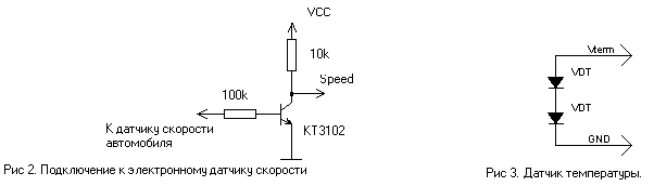 The connection of the speed sensor depends on the vehicle. Modern cars, as a rule, are equipped with an electronic speed sensor and can be connected to the device through a simple circuit shown in Figure 2. If the car has a mechanical speedometer drive, you need to use a converter, such as in taxi cars. To power the circuit, a stabilized voltage source Vcc = 5V is required. It is not shown on the diagram, because. Currently, there are a large number of integral stabilizers (eg 7805). Correct operation of the device is impossible without its configuration (calibration). You can enter the calibration mode by holding the K1 button for more than 30 seconds, until the indicator briefly shows "SPEEd", and then "SP0000". During calibration, the buttons perform the following functions: K1 (hold for more than 5 seconds) - saving the calibration constants for the selected channel; K2 - zero point; K3 - point one hundred); K4 - change of calibration channel (SPEEd, tin, tout, EnGinE, Ubatt); K5 - exit from the calibration mode. To calibrate the speedometer and distance counter, you must select the "SPEEd" channel, record the zero point (K2), drive exactly one kilometer, record the hundred point (K3), record the constants (K1). When driving, the display looks like "SPXXXXX", where XXXXX is the hexadecimal number of pulses received from the speed sensor. When calibrating thermometers, temperature sensors are placed in melting ice (0°C), the zero point is memorized, then the sensor is placed in boiling water (100°C), the 1 point is memorized, and finally, by pressing and holding K0, we memorize the constants in the memory chip. The voltmeter is calibrated at the 10V point (zero point), and at the XNUMXV point (hundred point). The zero and hundred points must be stable (as indicated on the display) and stored in memory for all channels. If the constant is successfully written, the inscription "SAVE" is displayed, and if an error occurs, "Error", in this case you need to try again, and if it fails, replace the memory chip. You can change the time by holding down the K1 button for more than 5 seconds, until the time indication starts to "flash". Use buttons K2 and K3 to change the hours and minutes, respectively. Then press K5, the display will show "SAVE" if the save was successful or Error otherwise.  (click to enlarge) You can use the device not only in a car, but, for example, in everyday life, like a clock - a thermometer. The device has been operated on a car for several months, and during this time there has not been a single significant failure, despite all the simplifications. Author: Andrey Irenokovich Klochko, andron74 {dog} mail.ru; Publication: cxem.net
See other articles Section Automobile. Electronic devices
Artificial leather for touch emulation
15.04.2024 Petgugu Global cat litter
15.04.2024 The attractiveness of caring men
14.04.2024
▪ Amaterske Radio magazines (annual archives) ▪ book Equivalent circuits and parameters of semiconductor devices. Bocharov L.N., 1973 ▪ Ganymede article. Popular expression ▪ Article Legal Specialist. Job description ▪ reference book Foreign microcircuits and transistors. Series X
Home page | Library | Articles | Website map | Site Reviews
www.diagram.com.ua |

 Leave your comment on this article: