|
|
ENCYCLOPEDIA OF RADIO ELECTRONICS AND ELECTRICAL ENGINEERING Radio station at 5650 ... 5670 MHz. Encyclopedia of radio electronics and electrical engineering
Encyclopedia of radio electronics and electrical engineering / Civil radio communications
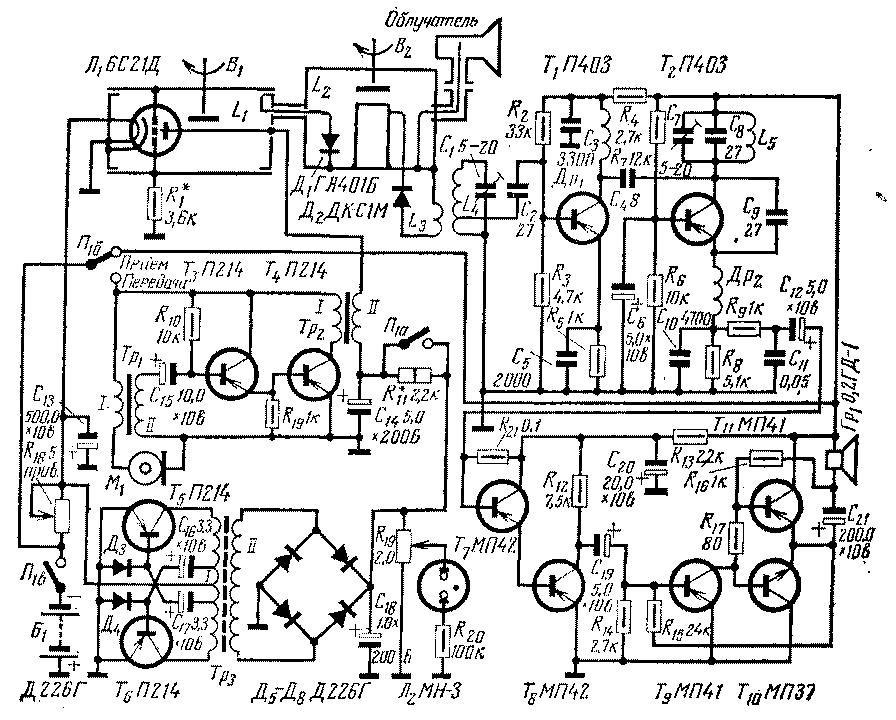
The radio station is intended for communication in field and stationary conditions. It is small, light weight and portable. The extreme simplicity of the circuit and the absence of scarce parts makes it possible to make it for a radio amateur of average qualification. The radio station is assembled according to the transceiver scheme. The master oscillator, tripler, output circuit and antenna are used in both receive and transmit modes. The receiver is assembled according to the super-super-regenerator circuit with an intermediate frequency of 30 MHz (more precisely, the intermediate frequency is selected during tuning). The rotating antenna device of the radio station consists of a parabolic reflector with a horizontal dimension of 50 cm and a vertical dimension of 26 cm. Schematic diagram of the radio station is shown in fig. 1. The transmitter master oscillator operates at frequencies of 1880-1890 MHz on the L1 lamp and the L1 coaxial resonator. The frequency tripler is assembled on diode D1. Coaxial resonator L2., tuned to the middle frequency of the range (5660 MHz). The tripler is connected to the circuit using a connection coil, which is the diode D1 itself. The voltage removed from the L2 circuit is fed through a coaxial waveguide to the antenna feed. The modulator is assembled on a composite transistor T3-T4. The radio receiver works as follows. The signal received by the antenna enters the coaxial resonator L2. Thus, the signal voltage and the local oscillator voltage are applied to the diode D2. The difference frequency allocated using the circuit L4C1 is fed to the first IF amplifier, assembled on the transistor T1. Next, the signal is fed to the super-regenerative detector on the transistor T2. The detected signal is amplified by a low-frequency amplifier based on T7-T11 transistors. The possibility of using a transceiver circuit is due to the choice of the operating mode of the master oscillator lamp. It is known that for the operation of the radio station both in the receive mode and in the transmit mode, at the same frequency, it is necessary that the local oscillator frequency for the receiver be different from the transmitter frequency by the IF value. In this radio station, the oscillation frequency of the master oscillator increases during the transition to transmission due to an increase in the anode current of the lamp (when the resistor R11 is closed). The radio station is tuned using the capacitive probe B1. Rotating B1 by 180° is enough to cover the range. Details. Coaxial resonator L2 consists of two parts (see fig.2): anode and cathode plungers from the resonator to the lamp 6S21D. The plunger collets are removed, and a silver-plated rod is soldered into the anode plunger, a tuning screw is soldered into the cathode plunger (also from the resonator from the 6S21D lamp). After installing the connection turns, both plungers are joined and carefully soldered. Coaxial waveguides from the local oscillator and antenna are soldered directly to the resonator body with an external braid. In the absence of a second set of resonators from a 6S21D lamp, the circuit can be machined from bronze or made from sheet metal according to the specified dimensions. One should not strive to obtain a high quality factor of the resonator, since its bandwidth should not be less than 35-40 MHz. The radio's antenna is detachable and mounted on the chassis using a high-frequency coaxial sliding connector. Antenna feed is a horn with an extended vertical part (fig. 3). To adjust the irradiator there is a movable plunger. An irradiator is made of silver-plated copper sheet 0,5-1,5 mm, the seams of the horn are carefully soldered. The manufacture of the reflector begins with drawing a parabola with a focal length of 17,5 cm on thick cardboard. (fig. 4). According to this template, strips of aluminum sheet with a thickness of 1-1,5 mm are cut out. The slots in them are sawn in such a way that the vertical and horizontal strips enter each other freely and their planes are parallel to the focal axis of the parabola. Assembling the reflector frame (fig. 5), with the help of wires, a metal mesh (with cells of 1-4 mm) is strengthened in the form of horizontal stripes 35 mm wide. The reflector is mounted on the antenna connector using a square so that it can move in a horizontal plane relative to the antenna feed during tuning. As a master oscillator, a ready-made resonator with a 6S21D lamp is used without alteration. Before installing the generator, you must first "drive" it into the range, for which, having temporarily assembled the lamp power circuit and controlling the frequency of the generated oscillations by the wavemeter, reduce the length of the anode resonator to obtain a frequency of 1885 MHz. Check the coverage in the range 1880-1890 MHz; by changing the position of the cathode plunger of the resonator, one finds one at which the output power will be maximum. Coils L3, L4, L5 are frameless, wound with a forced pitch (0,3-0,6 mm) with 1,0 mm silver-plated wire. Coil L3 contains 3 turns, L4 - 12 turns, L5 - 8 turns. The tap in the L4 coil is made from the first turn, counting from the grounded end. The outer diameter of all coils is 8 mm. Inductors Dr1 and Dr2 are wound on VS-0,5 1,0 MΩ resistors with a 0,12 mm wire until filled. Transformer Tr1 is wound on the core from the output transformer for pocket receivers. The primary winding contains 80 turns of PEV 0,1, the secondary - 3500 turns of PEV 0,05. Transformer Tr2 is wound on a core made of Sh5 plates; the thickness of the set is -0,5 cm. The primary winding contains 100 turns of PEV 0,6, the secondary - 1150 turns of PEV 0,18. Transformer Tr3 is wound on a ferrite W-shaped core with a cross section of 0,5 cm2. The primary winding contains 96 turns of PEV 0,8 wire with taps from 36, 48, 60 turns. Secondary winding - 1200 turns of PEV 0,2 wire. The radio station is mounted on a U-shaped chassis made of duralumin 1-2 mm thick with a removable bottom. The 8 V power supply (6 KBS-L-0,50 batteries) and the converter are separated from the rest of the circuit by a partition (Fig. 6). The carbon microphone and loudspeaker are mounted on the front panel, the bass amplifier board is mounted directly on the loudspeaker and is attached to the front panel with two screws. Lamp L1 with a resonator is installed on an insulated base and is attached to it with the help of clamps. Handles are displayed on the front panel of the radio station: switch P1 "reception-transmission", radio settings (screw B1, elongated with an insulating handle) and resistor R18. The tuning of the radio station begins with checking the generation of the master oscillator. Then, using a wavemeter, the master oscillator is more accurately tuned to the range of 1880-1890 MHz (by moving the anode plunger). Having connected the antenna, pre-tune the resonator L2 (with a tuning screw B2) according to the readings of the field strength indicator installed in front of the irradiator (switch P1 in the transmission position). They begin to select the resistance of the resistor R11, for which they temporarily replace it with a variable. By controlling the frequency drift of the master oscillator using the wavemeter, the resistance is changed until the frequency drift is 10 MHz. The resulting resistance is measured, and a constant resistor is soldered into the circuit. By setting the field strength indicator on the focal axis of the parabola at a distance of 70-80 cm, by moving the antenna reflector, a position is found at which forward radiation will be maximum. By moving the plunger in the irradiator, the radiation maximum is found. After that, by gradually shortening the pin in the antenna feed, its length is determined at which the radiation will be maximum. In conclusion, the settings (when communicating with the correspondent) with the tuning screw B2 adjust the resonator L2 to the maximum reception. The radio station was tested for communication with the UA3TN radio station. Communication with RS 57 in both directions took place at a distance of up to 1 km. Fig.2. Resonator L2
Authors: A. Bondarenko (UA3TEG), N. Bondarenko (UA3TED); Publication: N. Bolshakov, rf.atnn.ru
A New Way to Control and Manipulate Optical Signals
05.05.2024 Primium Seneca keyboard
05.05.2024 The world's tallest astronomical observatory opened
04.05.2024
▪ Underwater Wi-Fi to watch the oceans ▪ Ordinary dogs accepted the robot into their company ▪ Plastic for household recycling ▪ People with no sense of smell can also smell. ▪ Electronics powered by the ear
▪ section of the site Tips for radio amateurs. Selection of articles ▪ article Threats to information security of Russia. Basics of safe life ▪ article What man-made objects on Earth are visible from space? Detailed answer ▪ article Doctor of the day hospital. Job description ▪ article Refinement of the LED lamp. Encyclopedia of radio electronics and electrical engineering ▪ Chameleon ball article. Focus Secret
Home page | Library | Articles | Website map | Site Reviews www.diagram.com.ua |


 Arabic
 Bengali
 Chinese
 English
 French
 German
 Hebrew
 Hindi
Hindi Italian
 Japanese
 Korean
 Malay
Malay Polish
 Portuguese
 Spanish
 Turkish
 Ukrainian
 Vietnamese


 Leave your comment on this article: