|
|


 Arabic
 Bengali
 Chinese
 English
 French
 German
 Hebrew
 Hindi
Hindi Italian
 Japanese
 Korean
 Malay
Malay Polish
 Portuguese
 Spanish
 Turkish
 Ukrainian
 Vietnamese
|
ENCYCLOPEDIA OF RADIO ELECTRONICS AND ELECTRICAL ENGINEERING Tunable low-pass filter in an FM transceiver. Encyclopedia of radio electronics and electrical engineering
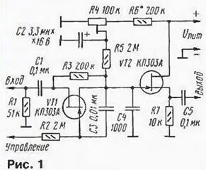
Encyclopedia of radio electronics and electrical engineering / Civil radio communications Radio amateurs know how difficult it is to receive weak signals from a correspondent against the background of the noise of an FM transceiver. You can slightly improve reception if you enter a low-pass filter into the transceiver. Noise when receiving FM signals decreases only when the signal of the correspondent exceeds a certain threshold. To reduce their level when receiving weak signals, you can apply a low-pass filter (LPF) with a cutoff frequency of 2...3 kHz. However, when receiving powerful signals, the same low-pass filter noticeably worsens the quality, as it “cuts off” high frequencies and makes the sound “mumbling”. Installing a low-pass filter with manual adjustment (tone control) is inconvenient, since there is no free space on the front panel of the transceiver, and it is tiring to constantly use such a control. The way out of this situation can be the use of a tunable low-pass filter, the bandwidth of which would automatically change in accordance with the level of the received signal: the stronger the signal, the wider the bandwidth. This will improve the reception of weak signals and, at the same time, not worsen the reception of powerful ones. The control signal for such a tunable low-pass filter can be a constant voltage from the output of the AM detector, the AGC system, or the received signal level indication circuit (S-meter). The filter circuit is shown in fig. 1. It is assembled on two field-effect transistors, one of them - VT1 - performs the functions of an electronically adjustable variable resistor, and the source follower is assembled on the second (VT2). The filter is included in the break in the circuit going from the movable contact of the volume control to the UZCH input.
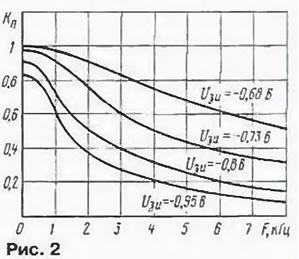
The RC circuit, consisting of resistor R3, the channel resistance of the field-effect transistor VT1 and capacitor C4, is a single-link low-pass filter. By changing the channel resistance of the transistor VT1, you can vary the cutoff frequency of the filter. And this resistance depends on the blocking gate-source voltage. Capacitor C3 reduces the non-linear distortion that may occur due to the modulation of the transistor channel resistance by the processed signal. Resistor R3 limits the change in the cutoff frequency of the low-pass filter. On fig. 2 shows the amplitude-frequency characteristics of the device at different gate-source voltages.
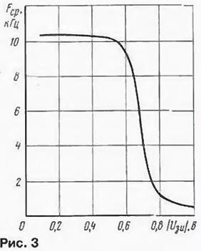
At a voltage of less than 0,5 V, the upper limit of the LPF passband exceeds 10 kHz, and the filter does not affect the passband of the low-frequency path (Fig. 3).
The control signal must be positive polarity. If you use the constant component of the output signal of the AM detector, then a low-pass filter with a frequency of several hertz must be installed in the device control circuit. Adaptation of the device to specific signal levels is carried out by a tuning resistor R4. Resistor R4 - SPZ-19a, the rest - MLT, S2-33, R1-4, capacitor C2 - series K50, K52, K53. Transistors can be replaced with KP303B. If it is necessary to make the control characteristic smoother, it is necessary to use transistors with a larger blocking voltage - KP303V, KP303G. In this case, the resistor R6 must be used with a resistance 2 ... 3 times less. Depending on which transceiver the device will be installed in, the elements R1, C1, C5 may be excluded. All parts are placed on a printed circuit board made of one-sided foil fiberglass, a sketch of which is shown in Fig. 4.
The device was installed in the Dragon SS-485 transceiver. The wire from the moving contact of the volume control to the resistor R130 (10 kOhm) was cut. The input of the device is connected to a moving contact, and the output is connected to the resistor R130. Resistor R2 is connected to the connection point of diode D9 and trimmer resistor RV1 (50 kOhm). Power is supplied from the power output of the UZCH chip IC3. Resistor R4 sets the initial blocking voltage on the transistor VT1. You can do this by ear. They find such a position of the R4 engine, in which, during the reception of weak signals (0 ... 1 points on the S-meter), a decrease in high-frequency noise would be noticeable, and when receiving more powerful signals, the low-pass filter band expanded. To make this effect more noticeable, it is necessary to install another 3 uF capacitor in parallel with capacitor C0,22 during tuning. Author: I.Nechaev (UA3WIA)
The world's tallest astronomical observatory opened
04.05.2024 Controlling objects using air currents
04.05.2024 Purebred dogs get sick no more often than purebred dogs
03.05.2024
▪ Ingenic tablet with Android 4.0 for $120 ▪ Biohybrid fish from human heart cells ▪ Efficient infrared LED crystal from Osram ▪ Blue and Ultra SSDs up to 1TB ▪ Biometric bank card Mastercard
▪ section of the site for those who like to travel - tips for tourists. Article selection ▪ article The Quiet American. Popular expression ▪ croupier article. Job description ▪ article Frame - from a ballpoint pen. Encyclopedia of radio electronics and electrical engineering ▪ article A man passes through glass. Focus secret
Home page | Library | Articles | Website map | Site Reviews
www.diagram.com.ua |

 Leave your comment on this article: