|
|


 Arabic
 Bengali
 Chinese
 English
 French
 German
 Hebrew
 Hindi
Hindi Italian
 Japanese
 Korean
 Malay
Malay Polish
 Portuguese
 Spanish
 Turkish
 Ukrainian
 Vietnamese
|
ENCYCLOPEDIA OF RADIO ELECTRONICS AND ELECTRICAL ENGINEERING Micro radio station. Encyclopedia of radio electronics and electrical engineering
Encyclopedia of radio electronics and electrical engineering / Civil radio communications
When installing large antenna masts, several people are usually involved. Moreover, they can be at such a distance at which it is no longer possible to ensure reliable synchronization of their actions simply by voice (especially in conditions of external noise, wind, etc.). And without synchronous actions of the team, the mast may collapse during lifting, with all the ensuing consequences. When the motorcycle is moving, negotiations between the driver and the passenger are almost impossible. Sometimes wired intercoms are used to provide communication between the driver and the passenger. But they are dangerous to use, because if the wire falls, it can aggravate the emergency situation, turning into a "noose". The microradio station in the helmet is devoid of this very significant drawback. This list can be continued: climbers on a difficult route, kayak travelers on fast rivers, etc. The radio station, which is described in the published article, is designed to solve just such problems, and its use can save human lives in certain situations. This radio station uses "frontal" reception to free the operator's hands: the transition from reception to transmission is provided by the VOX (voice control) system. Naturally, full duplex would be more suitable for this kind of communication - as in a conventional telephone. And this problem, apparently, can be solved by not very complicated means, since the problem of clogging the receiver with its transmitter is minimized due to the very low power of the transmitter. To solve the problem of organizing radio communications over very short distances, the amateur band of 10 meters and the adjacent CBS band are optimal. Circuitry at frequencies corresponding to these ranges is relatively simple, and designs are easy to reproduce and adjust even with little experience at high frequencies. The practical design of the radio station, which is discussed in this article, was made on the CB band. When repeating it in the version for the amateur range of 10 meters, it will most likely be necessary to replace only the quartz resonators in the receiver and transmitter, since the adjustment limits of the inductors should be enough for the operating frequency within this range as well. The receiver and transmitter paths of this microradio station are completely separate. They are connected only by the control circuit, which turns off the receiver when transmitting. The transmitter circuit is shown in fig. 1. It consists of a master oscillator, an output stage, a microphone amplifier and a voice control unit for turning on the transmitter (and turning off the receiver). The master oscillator is made on a transistor VT5 according to the "capacitive three-point" scheme. The generation frequency is determined by the quartz resonator ZQ1. A VD3 varicap is connected in series with it, which is used for frequency modulation of the generator. The power amplifier is made on the transistor VT6. The oscillatory circuit L2C11 in its collector circuit is tuned to the operating frequency of the radio station.
A microphone amplifier is made on the VT1 transistor and the DA1 chip, the output signal of which is fed to the VD3 varicap. The transmitter is activated by voice. The signal from the output of the DA1 chip is fed to the rectifier VD1VD2R8C5. A constant voltage from the output of this rectifier opens transistors VT2 and VT3. The latter supplies power to the high-frequency stages of the transmitter. The transmitter turn-off delay can be calculated using the formula: toff =C5 x R8 x R9/(R8+R9). Usually it is chosen within 0,4 ... 2 s. This choice is determined by the characteristics of the operator's speech (its pace, the duration of speech pauses). The desired delay is set by selecting the capacitor C5. Through the transistor VT4, the control signal is fed to the receiver, turning it off for the duration of the transmission. The receiver circuit is shown in fig. 2. A radio frequency amplifier is assembled on the transistor VT1. Its input (L1C2C3) and output (L3C5C6) circuits are tuned to the operating frequency of the radio station. The connection of the receiver with the antenna is transformer. Germanium diodes VD1 and VD2 limit the input signal level to approximately 0,2 V, thereby eliminating the failure of the transistor VT1 when the radio is transmitting.
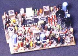
The main RF signal processing takes place in the DA1 chip. It includes a local oscillator (its frequency is set by a ZQ1 quartz resonator), a mixer, on the load of which (ZQ2 filter) an intermediate frequency signal of 465 kHz is emitted, a frequency detector with an L5C10R3 phase-shifting circuit, a noise suppressor amplifier and a preliminary ultrasonic frequency converter. On the operational amplifier DA2 and transistors VT5 and VT6, an AF power amplifier is assembled. Its feature is low power consumption in all modes. The DC amplifier (transistors VT3, VT4) operates in key mode. It coordinates the output of the squelch with the control input DA2. This eliminates the influence of changes in the supply voltage of the radio station (when the batteries are discharged) on the operation of the squelch. The squelch threshold is adjusted by resistor R6. When a useful signal appears, high-frequency noise decreases at the output of the detector and the voltage level at pin 13 of DA1 changes abruptly from high to low. Transistors VT3 and VT4 open, allowing the UZCH to work. Transistor VT2 supplies power to the RF part of the receiver when the transmitter is turned off. When pin A is high, VT2 is closed and the RF and IF paths of the receiver are de-energized. At a low level at pin A, transistor VT2 opens to saturation and the radio turns on to normal operation. The receiver may have its own antenna, or it may be connected to the transmitter's antenna. The radio station is mounted on a printed circuit board made of double-sided foil fiberglass with a thickness of 1,5 mm (Fig. 3). The red line conditionally separates the transmitter and receiver.
The foil on the side of the parts is used only as a common wire and screen. Corresponding selections are made (etched) in it in places where conductors are skipped (they are not shown in Fig. 3). Foil connections to "grounded" terminals of resistors, capacitors, and other items are shown as black squares. The same squares, but with a bright dot in the center, mark the wire jumpers that connect certain fragments of printed wiring with the foil of the common wire, and the "grounded" pins of the microcircuits. The transmitter coil (Fig. 1) L1 has 25 turns wound with PEVSHO 0,12 wire on a frame with a diameter of 5 mm, which is screwed into the board (Fig. 4). The frame has a M3x9 carbonyl trimmer.
The design of the coil L2 and its mounting on the board are shown in fig. 5. Its 16 turns are wound in a row with PEV-2 0,33 wire. Coil L3 (four turns of PEVSHO 0,2 wire) is wound over L2 at its "cold" (HF) end. The coil trimmer L2 is the same as L1. Microphone BM1 - CZN-15E. You can take an electret microphone and another type.
Receiver coils (Fig. 2) L1, L3 and L5 - shielded, factory-made, KVP type, with communication coils. They were purchased in the Moscow shop "Chip and Dip". Inductance L1 and L3 - 1 μH, L5 - 240 μH. The coupling coils in L3 and L5 are left unused (they must not be closed!). It is permissible to use other coils with the appropriate inductance and acceptable dimensions. The contact petals of the screens are bent at a right angle and soldered directly to the foil of the common wire. Coil L4 - 10 turns of wire PEVSHO 0,12. It is wound coil to coil on a frame with a diameter of 5 mm (Fig. 4). Dynamic head BA1 - 0,25GDSH-7 with a resistance of 50 ohms. The quartz resonators of the radio station can be soldered into the holes intended for them. But, as experience shows, the frequency of a quartz resonator sometimes differs significantly from the nominal value affixed to its case. To be able to change quartz resonators without soldering, miniature sockets are installed on the board from a connector designed for a pin with a diameter of 1 mm. They can be mounted on the board as shown in Fig. 6.
All fixed resistors in the radio station are MLT-0,125, tuning resistors are SP3-38a. Oxide capacitors C2 and C10 (see Fig. 1) and C22 (Fig. 2) have a diameter of 6 mm, and C21 (Fig. 2) - 5 mm. These capacitors are foreign-made (domestic ones have large dimensions). They are mounted on the board as shown in Fig. 7. In order to avoid short circuit, the foil under the capacitor has an annular sample. Capacitors C3, C5 (see Fig. 1) and C11 (see Fig. 2) - K53-30. Others - KM-6, K10-17b, KD, etc.
To tune the radio station, it is desirable to have a frequency meter, for example, Ch3-57, an oscilloscope and a CB radio station with the desired channel. If the oscilloscope "does not see" a signal with a frequency of about 27 MHz, or it cannot be used to measure the signal level, then an RF voltmeter with a "~ U" scale of 0,3 V, for example, A4-M2, will also be required. The setup starts with the transmitter. It is transferred to the continuous radiation mode by connecting the collector of the transistor VT3 and the left (according to Fig. 1) lining of the quartz resonator ZQ1 to the common wire. By connecting the oscilloscope to the emitter of the transistor VT5, visually evaluate the frequency of the master oscillator. If it is about 9 MHz (27/3), then the installed resonator is harmonic and the frequency indicated on its body is the third harmonic of the fundamental resonance. It is better to replace it with a resonator excited at the fundamental frequency. If a harmonic resonator is used, then the inductance of the coil L1 must be increased by about nine times, i.e., the number of turns must be three times greater. Then, an antenna equivalent is connected to the L3 coil - a load with a resistance of 50 ohms and an RF voltmeter. By adjusting the L2 coil, the L2C11 output circuit is adjusted to the maximum voltmeter reading. By removing the jumper connecting the output of the quartz resonator to the common wire (thus turning on the frequency modulator), make sure that the generator continues to work and by adjusting the coil L1 bring its frequency exactly to the working one. The frequency meter is connected to the antenna load of the transmitter. It is easy to bring the microphone signal to the desired level with the resistor R2 or by changing the gain of the cascade on the operational amplifier DA1 (k=R5/R4). By shunting the resistor R5, the gain of the path is reduced, and by shunting R4, it is increased. The gain of the microphone amplifier (modulation level) is controlled by the low-frequency signal at the output of the control receiver. It must have sufficient volume, but not "fly out" of the channel, which is usually accompanied by strong distortion. The constant voltage at the output of DA1 should be within 2,5 ... 3,5 V. If it is less than 2 V, it is increased by shunting the capacitor C3 with a resistor close in resistance to R5. The constant voltage at pin 6 of DA1 should remain practically unchanged when the supply voltage drops to 4,5 ... 5 V. The function of the stabilizer, which fixes this voltage and, accordingly, minimizes the “drift” of the transmitter frequency when the supply voltage changes, is performed by the transistor VT1, operating here in the mode of a current generator. Then they check the operation of the "voice" key: they make sure that the resistor R2 can set one or another acoustic threshold for turning on the transmitter. In table. 1 shows the dependences of the current consumed by the transmitter in the transmission mode Itrans, output power Pout, carrier frequency drift Df and standby current Idej (no modulation, transmitter off) on the power supply voltage Upit.
To tune the receiver (Fig. 2), you can use a CB radio station located at a distance of 1 ... 2 m, operating on an antenna equivalent. It will act as an RF generator. An oscilloscope is connected to pin 5 of the DA1 microcircuit (the output of the IF filter) (sensitivity is 10 mV per division) and by adjusting the RF circuits (including L4) the maximum level of the IF signal is achieved. In the process of tuning with an increase in the level of the output signal, the radiating station is moved away, and tuning is completed at an extremely small input signal. The phase-shifting circuit L5C10 of the receiver is adjusted according to the signal of the correspondent working in FM: the coil trimmer L5 is left in the position that the loudest signal of the best quality will correspond to. The dependence of the current consumed by the receiver in the standby reception mode Idezh (UZCH is closed by a noise suppressor) and the operating mode current Iwork (UZCh is open, free channel noise is heard) on the power supply voltage Upit is shown in Table. 2. In a receiver without URF, Idezh is lower by 0,7 ... 1,8 mA (at Upit 5 ... 10 V).
The radio station works with any 50-ohm antenna of an acceptable length, for example, from the Dragon SY-101 radio station (length 23 cm, CP-50 type connector). Home-made antennas are also suitable (see the article by G. Minakov, M. Fedosov, D. Travinov "Hummingbird" radio station in "Radio", 1999 But in all cases it is recommended to connect the foil of the common wire of the board (better - at the point where the L3 coil is connected to it transmitter) with something that could serve as a counterweight in the resulting antenna system (in conventional "portables" the operator himself serves as a counterweight). The "range" of the station will noticeably increase if a piece of mounting wire 1 ... 1,5 long is used as a counterweight, XNUMX m The radio receiver may have its own antenna. Since there are less stringent requirements for tuning and matching the receiving antenna, a simple piece of mounting wire 20 ... 30 cm long is quite enough. The low power consumption of the radio station in the transmission mode makes it possible to use small-sized and light sources of small capacity for its power supply, including batteries of galvanic cells. So, with a ratio of the time spent in standby mode to the time of active operation of 10/1, a radio station with a nine-volt "Korund" (its dimensions are 26,5x17,5x48,5 mm, weight 46 g, electrical capacity 620 mAh) will be able to work 70 ... 100 h, and with a six-volt battery type 476A (diameter 13 mm, height 25 mm, weight 14 g, capacity 105 mAh) - up to 15 ... 20D-7. The final design of the radio station depends on its purpose. Structurally, it can be made in the form of a single unit, having only an external microphone-telephone headset. But when placing the station, say, in a protective helmet of a motorcyclist, it is more convenient to deal with its individual components: transmitter, receiver, power supply (main or backup), loudspeaker, microphone, etc., mounting each of them as the operating conditions require. and will be user friendly. Two resistors, which are usually elements of the operational control of the radio station, are made trimmers. This is the resistor R2 (see fig. 1), which sets the threshold for turning on the transmitter (extraneous acoustic noise and rustles should remain under the threshold), and R6 (see fig. 2) is the threshold of the noise suppressor, which turns on the ultrasonic frequency of the station only when it appears in the channel the carrier connection is high enough. One or another position of these regulators is set in advance, before starting work. Author: Yuri Vinogradov, Moscow
A New Way to Control and Manipulate Optical Signals
05.05.2024 Primium Seneca keyboard
05.05.2024 The world's tallest astronomical observatory opened
04.05.2024
▪ AMD FirePro S9300 x2 Dual Processor Accelerator ▪ LG to launch phone with flexible OLED display
▪ site section Clocks, timers, relays, load switches. Article selection ▪ article Drugs and the dangers of their use for health. Basics of safe life ▪ article Why was an American WWII pilot proud of a downed American transport? Detailed answer ▪ article Podophyllum thyroid. Legends, cultivation, methods of application ▪ article Semipermeable septum in a plant cell. Chemical experience
Home page | Library | Articles | Website map | Site Reviews
www.diagram.com.ua |

 In most cases, when creating a radio station, they seek to increase the range of its action. However, there are applications where it is not the communication range that comes to the fore, but the convenience of using it. And first of all - the ability to use the radio station, leaving both hands free. Not an obstacle for these applications will be the minimum weight and dimensions of the radio. Here are some examples.


 Leave your comment on this article: