|
|


 Arabic
 Bengali
 Chinese
 English
 French
 German
 Hebrew
 Hindi
Hindi Italian
 Japanese
 Korean
 Malay
Malay Polish
 Portuguese
 Spanish
 Turkish
 Ukrainian
 Vietnamese
|
ENCYCLOPEDIA OF RADIO ELECTRONICS AND ELECTRICAL ENGINEERING Double tube superheterodyne. Encyclopedia of radio electronics and electrical engineering
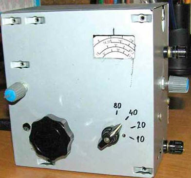
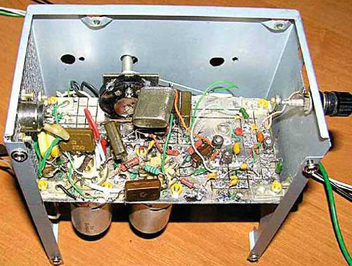
Encyclopedia of radio electronics and electrical engineering / Civil radio communications The theme of retro receivers, in particular regenerative ones, is comprehensive and very fruitfully developed on many sites on the Internet. At one time she was very interested in me. As a result, the idea arose to make a simple single-tube regenerator, which was subsequently converted into a simple, but multi-range superheterodyne with little blood. The design of a single-tube regenerative receiver based on a double triode 6N9M (6N9S) [1], remarkable for its simplicity and elegance, was taken as a basis, which, when the design was repeated, was replaced by its modern analogue 6N2P. During the testing of the prototype, some improvements were made: - environmental protection was introduced in the second stage (ULF) and increased in the first (actually regenerator). This became possible due to the use of a specific feature of triodes - a relatively large permeability or, if you like, a significant effect of the anode load on the grid-cathode circuits. Anode resistors of high resistance create a sufficiently large "internal" OOS, equivalent to introducing a resistance equal to Ra / c into the cathode, in our case it is 47 kOhm / 100 \u470d XNUMX Ohm, which ensures high stability of the selected mode; - removed high voltage from headphones (it's kind of creepy to realize that 200 V is applied to the head); - transition and blocking capacitors now perform the functions of single-link low-pass and high-pass filters, and their capacitances are selected so as to provide a frequency band of 300 ... 3000 Hz of the low-frequency path. As a result, the receiver has high stability (at 80 meters you can listen to the station for a long time without any adjustment!) And high sensitivity, good repeatability (due to OOS, its parameters do not depend much on the spread of lamp characteristics) and very simple control. On the basis of this regenerator, a two-tube four-band superheterodyne was built. Photos of its design are shown in fig. 1 - fig. 3, and the diagram is in fig. 4. The radio receiver allows you to receive SSB and CW signals from amateur radio stations on the bands 80, 40, 20 and 10 meters. The sensitivity of the receiver when receiving in telegraph (autodyne) mode and a signal-to-noise ratio of 10 dB is not worse than 1 μV (at 10 meters), 0,7 μV (at 20 and 40 meters) and 3 μV (at 80 meters) .
A two-stage input attenuator on a variable resistor R1 ensures the normal operation of the receiver with any, including a full-size antenna. The input dual-circuit bandpass filter (PDF) - L2L4C2-C8C10-C19 is designed according to a simplified scheme so as to provide maximum sensitivity on a range of 10 meters. On the range of 80 meters, the PDF has increased attenuation, which reduces some of the gain redundancy in this range. For a range of 80 meters, this is a 1-V-1 direct amplification receiver with a regenerative detector and a low-frequency amplifier on a VL2 lamp (the VL1.2 lamp pentode works as a decoupling UHF), and on the remaining ranges - a superheterodyne with a variable IF and a local oscillator with quartz frequency stabilization . The local oscillator is made on the VL1.1 lamp triode and the ZQ1 quartz resonator according to the capacitive three-point scheme (Colpitz generator). On the bands of 40 and 20 meters, it operates on the fundamental harmonic of the resonator - 10,7 MHz, and on the band of 10 meters - on its third harmonic (32,1 MHz), for which, in this range, the anode load is made in the form of a resonant circuit L3C1, tuned to a frequency of 32,1 MHz. A mixer is assembled on the pentode of the VL1.2 lamp. The tuning range of the regenerative receiver, which plays the role of the IF path, regenerative detector and ULF in the structure of the superheterodyne, is chosen to be 3,3 ... 3,8 MHz (range 80 meters), which provides sufficient coverage in the HF bands. Accordingly, on the range of 40 meters, the overlap will be 6,9 ... 7,4 MHz, on 20 meters - 14 ... 14,5 MHz, on 10 meters - 28,3 ... 28,8 MHz. The supply voltage of the anode circuit and the incandescent lamps of the receiver must be stabilized. The question - is it necessary to stabilize the supply voltage (filament and anode) of the lamp regenerator often arises on different branches of the network forums, and the answers to it often give the most contradictory - from nothing to stabilize and rectify (and everything works fine) to the mandatory use of a completely autonomous , battery, power supply. Surprising as it may seem, the statements of both are true (!), it is only important to remember the main criteria (or, if you like, requirements) that both authors place on the regenerator. If the main thing is the simplicity of design, why stabilize the power supply? Regenerators of the 20-50s (and these are hundreds of different designs), made according to this principle, worked perfectly and provided quite decent reception, especially on broadcasting bands. But as soon as we put sensitivity at the forefront, and, as you know, it reaches a maximum at the threshold of generation - an extremely unstable point, which is influenced by numerous external changes in parameters, and fluctuations in the supply voltage are among the most significant, then the answer becomes obvious. If you want to get high results, you need to stabilize the supply voltage. The receiver is mounted in a case from an old computer PSU. Installation - hinged, made on a chassis board made of fiberglass laminated on both sides. The foil of one side is cut into rectangles that serve as contact pads, the foil of the opposite side is used as a common wire. Installation requirements are standard - maximum mounting rigidity and minimum length of RF conductors. The receiver is assembled from non-deficient parts. All blocking and transfer capacitors must be rated at least 250 V. Coils L2 and L4 are wound with PEV-2 wire 0,17 turn to turn on frames with a diameter of 8,5 mm with trimmers (from the IF circuits of color TVs). The number of turns is 13. The communication coil L1 contains 3 turns of a similar wire and is wound over the coil L2 from the side of the output connected to the common wire. Chokes L3, L5 - small imported. Coil L6 is wound with wire PEV-2 1 on a ribbed ceramic frame with a diameter of 35 mm. The number of turns is 11, the winding pitch is 2 mm, the tap is from the 2nd turn, counting from the output connected to the common wire. Despite the fact that, in principle, the regenerator can work (i.e., completely regenerate the circuit) with almost any coil, it is desirable that it has the highest possible constructive quality factor. This will allow, with the same results, to apply a smaller inclusion of the lamp in the circuit and, accordingly, reduce its destabilizing effect (both of itself and of the entire receiver and power sources). Therefore, the L6 coil is wound on a frame of a sufficiently large diameter. The best option would be to wind the regenerator coil on an Amidon brand ring magnetic circuit (for example, T50-6, T50-2, T68-6, T68-2). The number of turns of the coil to obtain the specified inductance can be calculated using any program. For example, the COIL 32 program [2] is convenient for conventional frameworks, and the mini Ring Core calculator [3] is convenient for Amidon rings. For starters, the tap position can be taken from 1/5...1/8 (for conventional frames) to 1/10...1/20 (for Amidon) the number of turns of the loop coil. Tuning capacitor C23 is a small-sized two-section KPI with an air dielectric. Its sections are connected in series to eliminate rustling and crackling, and the rotor and case are isolated from the chassis (a kind of differential capacitor). Depending on the limits of its capacitance change and the inductance of the L6 coil, it may be necessary to recalculate the capacitance of the stretching capacitors in order to obtain the required tuning range for the capacitance of the stretching capacitors. This can be done with the simple program KONTUR3C_ver. by US5MSQ [4]. Headphones for the radio receiver must be electromagnetic and necessarily high-resistance (with coils of electromagnets with an inductance of approximately 0,5 H and a DC resistance of 1500 ... 2200 Ohms), for example, TON-1, TON-2, TON-2m, TA-4, TA-56m. If desired, the receiver can be retrofitted with a power amplifier, assembling it according to the standard scheme on 6P14P, 6F3P or 6F5P lamps. In this low-tube receiver, the gain (c) of the regenerator lamp is of great importance, and the low current consumption of 6N2P is also nice - you can put an effective RC filter in the anode power circuit without bulky chokes or electronic filters / stabilizers. That's exactly what I did - and no background in the phones. However, you can use any double triodes (6N1P, 6N3P, etc.) without adjusting the circuit and with almost no damage (there will be less than twice the LF gain). On the other hand, with a higher anode current and the steepness of the lamps, instead of high-resistance headphones, you can connect an output transformer and use more affordable modern low-resistance phones with high sensitivity. Setting up the receiver is quite simple and standard. After checking the correctness of the installation, we connect the power of the receiver and measure the lamp modes for direct current. We turn on the range of 80 meters and set up the regenerator. Its tuning consists mainly in laying the tuning range from 3300 to 3800 kHz with a small (approximately 20 ... 30 kHz) margin at the edges, selecting the capacitances of the stretching capacitors C26, C27 and ensuring a smooth approach to the regeneration point. To set the range, we apply a signal from the GSS through an isolation capacitor to the grid of the VL1.2 lamp (pin 2). You may have to more accurately select the tap of the L6 coil, achieving the appearance of generation at the lower tuning frequency of 3300 kHz (the KPI capacitance is maximum) in the position of the variable resistor R12 slider (regeneration adjustment) closer to the lower output according to the circuit. When tuning up in frequency, the generation conditions will improve and a greater shunting effect of the resistor will be needed, i.e., the working position of the engine will shift closer to the center in the direction of the upper one according to the output circuit. We check the smoothness of the approach to the regeneration point, i.e. when moving the variable resistor R12 slider to the lower output according to the output circuit, noise and rustles should gradually increase to a maximum, then a slight click (or just a sharp noticeable decrease in noise) and their subsequent decrease (along with sensitivity ) as the generation level increases. When moving the engine back, the generation should disappear in the same position in which it originated. If the smoothness is not enough, you can reduce the anode current of the lamp (increasing the resistance of the anode resistor R13) and re-select the tap connection point, and so on until the desired result is obtained. Then we set up the PDF of the 80-meter range, for which we connect the GSS to the antenna input of the receiver and set the average frequency of the range on the generator to 3,65 MHz. We transfer the regenerator to the generation mode (autodyne mode) and with the capacitor C23 we “find” the GSS signal. With trimmers of coils L2 and L4, we adjust the PDF to the maximum signal. This completes the tuning of the range of 80 meters, and we do not touch the trimmers of these coils in the future. Next, we check the operation of the local oscillator. We connect an AC lamp voltmeter to the cathode of the VL1.2 lamp (pin 7) and control the local oscillator voltage level. We turn on the ranges of 40 and 20 meters in turn, check the presence of an alternating voltage level of 1 ... 2 Veff. Then we turn on the range of 10 meters and use the trimmer capacitor C1 to set the maximum generation voltage. It should be about the same level. If there is no industrial voltmeter, you can use the simplest diode probe, described in detail in [5], or an oscilloscope with a bandwidth of at least 30 MHz and a low-capacity divider (high-resistance probe). In extreme cases, the oscilloscope can be connected through a capacitor with a capacity of 3 ... 5 pF. We continue to tune the PDF, starting with a range of 10 meters. To do this, we connect the GSS to the antenna input and set the average frequency of the range on it - 28,55 MHz. We transfer the regenerator to the generation mode and, adjusting the KPI, "find" the GSS signal. Trimmer capacitors C8 and C19 (we don’t touch the coil trimmers!) We adjust the PDF to the maximum signal. Similarly, we adjust the ranges of 20 and 40 meters with trimmer capacitors C7, C15 and C6, C13, for which, respectively, the average frequencies of the ranges will be 14,175 and 7,1 MHz. The radio scale is disk mechanical with an overlap of 500 kHz. On 80 and 20 meters it is direct, and on 40 and 10 meters it is reverse (similar to the UW3DI transceiver). I would not introduce a digital scale into the design of the receiver. Firstly, the mechanical scale is simple, the calibration is stable and it is enough to carry it out only on a range of 80 meters. And on the remaining ranges, the markup is drawn with a simple recalculation according to the measured frequency of the stand generator. Secondly, the digital scale itself, in case of an unsuccessful scenario, can become a source of interference, and it will be necessary to think over the design well and, probably, introduce shielding at least of the regenerator coil (its sensitivity is a few microvolts!), And possibly also the scale itself . If you nevertheless enter it, it is better to connect it like this: - remove the signal from the local oscillator through the source follower on the KP303 transistor (KP302, KP307, BF245, J310, etc.), by connecting the transistor gate through a 1 kΩ resistor directly to terminal 7 of the VL1 lamp; - the regenerator, depending on the adjustment of the PIC, can have a very low voltage on the circuit (tens of millivolts), so the regenerator signal will require not only decoupling, but also amplification. This is best done on a double-gate field-effect transistor KP327 or BF9xx, connected according to the standard circuit with a bias voltage on the second gate of +4 V and a 1 kΩ resistor in the drain circuit. The first gate of the transistor is connected to the cathode of the VL2 lamp (pin 3) through a 1 kΩ decoupling resistor. This radio receiver was assembled a long time ago, and yet, a couple of years after manufacturing, I took this two-tube super from the far shelf, blew off the dust and turned it on .. It works, it's so nice that in two evenings of unobtrusive observations on each of the lower ranges (80 and 40 meters) signals were received from all ten amateur radio regions of the former USSR! Reception was carried out on an antenna 42 m long. Of course, the dynamic range and selectivity in the adjacent channel are not enough, but in the first case, a smooth attenuator helps, and in the second, a slight narrowing of the bandwidth (by the regeneration knob). A cardinal solution would be to switch to a less "populated" frequency, and yet, even in the "overpopulated" parts of the ranges, at least basic information can be received. But the main advantage of the receiver (apart from simplicity of design) is very good frequency stability. You can listen to stations for hours without tuning, and this is equally successful not only on the lower ranges, but also on 10 meters! I measured its sensitivity again - with a signal-to-noise ratio of 10 dB, everything corresponds to the above data. And if you bind to the output signal at a level of 50 mV (already a rather loud signal on TON-2 phones), then the result is as follows: at 10 meters - 1 ... 1,2 μV, at 20 meters - 1,5 ... 2 μV , at 40 meters - 3 ... 4 microvolts, at 80 meters - 7 ... 8 microvolts. Literature
Author: Sergey Belenetsky (US5MSQ)
Artificial leather for touch emulation
15.04.2024 Petgugu Global cat litter
15.04.2024 The attractiveness of caring men
14.04.2024
▪ Communication with sensors through the wall ▪ Kingston SSDNow E50 Solid State Drives ▪ Supersteel modeled after human bone ▪ The STAMP camera shoots at a speed of 4,4 trillion. fps
▪ section of the site The most important scientific discoveries. Article selection ▪ article Economic statistics. Crib ▪ article Why was the great Hercules forced to obey the insignificant Eurystheus? Detailed answer ▪ article diathesis. Health care ▪ article Photoelectronic alarm clock. Encyclopedia of radio electronics and electrical engineering ▪ article Signal strength indicators. Encyclopedia of radio electronics and electrical engineering
Home page | Library | Articles | Website map | Site Reviews
www.diagram.com.ua |


 Leave your comment on this article: