|
|


 Arabic
 Bengali
 Chinese
 English
 French
 German
 Hebrew
 Hindi
Hindi Italian
 Japanese
 Korean
 Malay
Malay Polish
 Portuguese
 Spanish
 Turkish
 Ukrainian
 Vietnamese
|
ENCYCLOPEDIA OF RADIO ELECTRONICS AND ELECTRICAL ENGINEERING Economical radio. Encyclopedia of radio electronics and electrical engineering
Encyclopedia of radio electronics and electrical engineering / radio reception At present, the efficiency of radio receivers is becoming increasingly important. As you know, many industrial receivers are not economical, but meanwhile, in many localities of the country, long-term power outages have become commonplace. The cost of batteries with frequent replacement also becomes burdensome. And far from "civilization" an economical radio receiver is simply necessary. The author of this publication set out to create an economical radio receiver with high sensitivity, the ability to operate in the HF and VHF bands. The result turned out to be quite satisfactory - the radio receiver is capable of operating from a single battery and is only slightly inferior in terms of the quiescent current to the design described in [1]. The receiver remains operational when the supply voltage drops to 1 V. The sensitivity of the receiver is very high - it was not possible to accurately measure it due to the lack of appropriate measuring equipment. Main Specifications
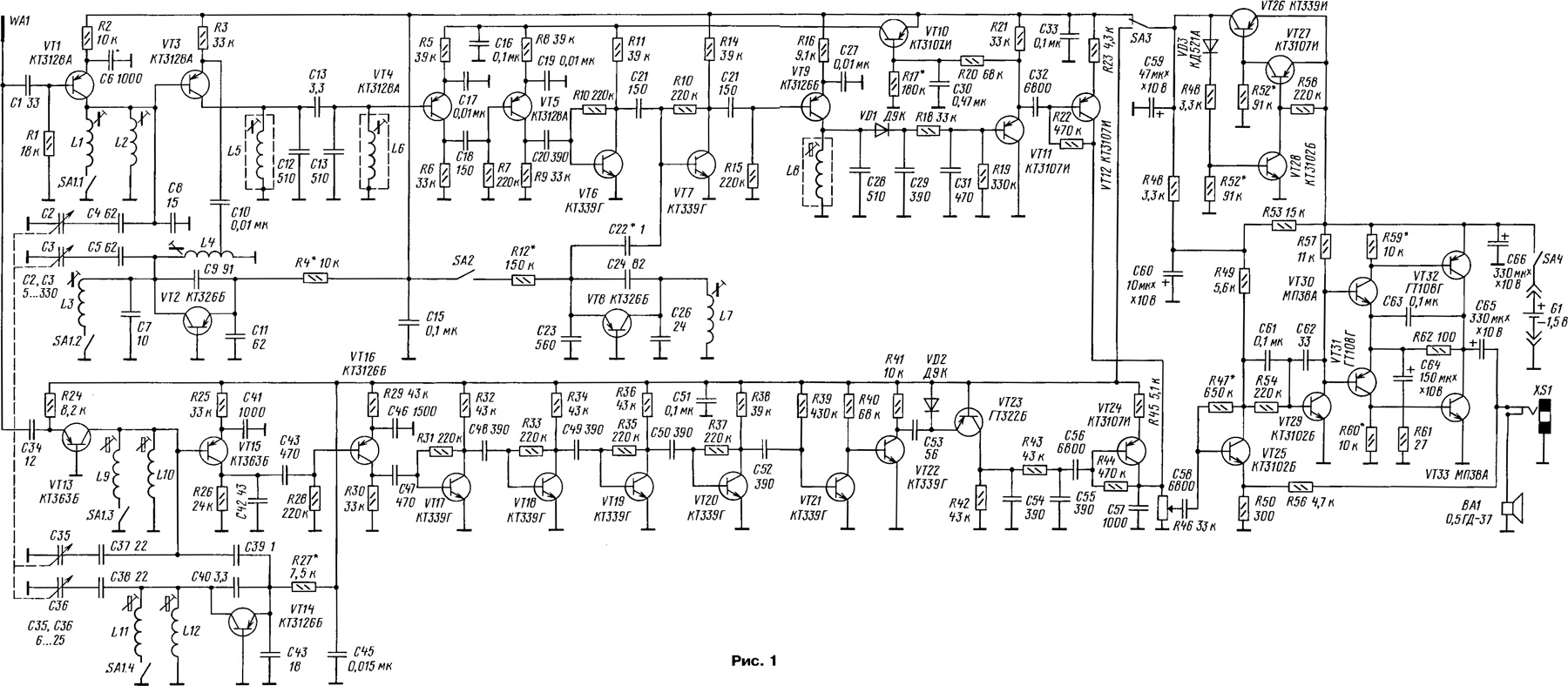
During the tests, the receiver worked daily for 9 hours instead of the subscriber loudspeaker. When using alkaline element type LR6 "ALKALINE", the operating time increases several times. The service life of such elements reaches 5 years, which makes them convenient for long-term use. To increase efficiency, the receiver had to be optimized, making each of its nodes as economical as possible. It was clear that the main power of the power supply would be consumed by the audio frequency amplifier, and it was to this node that special attention was paid. Tests of the housing from the SOKOL-404 receiver with a built-in loudspeaker 0.5GD-37 showed that for comfortable individual listening, an output power of 1 ... 3 mW is sometimes quite enough, and for reproducing such a signal with acceptable quality, the maximum amplifier power may not exceed 30 mW. For "quiet" small rooms, this value can be reduced by 2-3 times. Of course, it is important to have a high efficiency loudspeaker. Tests show that drivers with a cone diameter of less than 5 cm are generally very inefficient, making them unsuitable for an economical radio receiver. When developing the circuit, some features of the operation of transistors operating in microcurrent modes were determined. From the formulas given in [2], the transistor at lK = 10 μA has a large intrinsic emitter resistance, equal to about 2,5 kOhm. With such a current, even with |h21Э| \u40d 100, the input resistance of a cascade assembled according to a common emitter circuit reaches 0,4 kOhm, which makes it possible to successfully apply the full inclusion of the oscillatory circuit in the base circuit of the transistor. On the other hand, the slope of the transistor characteristic at such a current does not exceed XNUMX mA / V, therefore, to obtain a good gain, the load resistance of the cascade should be several tens of kilo-ohms. If the load is an oscillatory circuit, then to obtain a larger resonant resistance, you should choose a larger inductance value, and a smaller capacitance value. This is especially important for UHF cascades. It should also be borne in mind that the frequency properties of transistors at a current of 10 μA deteriorate several times due to the influence of the internal capacitances of the transistor. Therefore, for economical cascades, transistors with a low collector capacitance and a high cutoff frequency should be selected. The radio receiver brought to the attention of readers consists of two independent AM and FM paths, which made it possible to simplify the switching of bands to the limit. It may seem that the receiver circuit (Fig. 1) is too complicated and contains a lot of transistors, but transistors in plastic cases are now cheaper than capacitors.
Depending on the needs, the radio amateur can choose only one of the paths for himself or reduce the number of ranges. Both paths have a stabilized power supply of 0,93 V and operate on a common UZCH. The AM path is made on transistors VT1-VT12. The URC is assembled according to a scheme with a common emitter on a transistor VT1. The local oscillator is made according to the capacitive three-point circuit on the transistor VT2. When the contacts of the SA1 switch are closed, the URF coils L1, L2 and the local oscillator l_3, L4 are switched on in parallel in each pair, which corresponds to operation in the KV-2 subband. Transistor VT3 performs the functions of a mixer. The scheme of its inclusion is unconventional, however, it has already been used in [1]. The base and collector are connected together by direct current. In this case, the voltage at the emitter of the transistor is determined by the open p-n junction of the base-mitter and is approximately 0,5 V. This voltage is the power for the collector circuit. Since at low currents the saturation voltage of the transistor is usually 0,1 ... 0,2 V, the transistor creates a voltage swing of up to 0,3 V on the load, which is quite enough in this case. Thus, the current consumed by the stage is determined only by the resistance of the resistor in the emitter of the transistor. An IF signal with a frequency of 465 kHz is fed directly through a double-circuit filter to the base of the VT4 transistor, which, as already noted, has a high input impedance and the circuit almost does not shunt. The first three cascades of the IF are powered through the VT10 transistor, which, together with the VT11 transistor, work in the AGC amplifier. As the voltage at the output of the detector increases, the voltage at the emitter of the transistor VT11 also increases. This leads to a partial closing of the transistor VT10, and the gain of the first three cascades of the IF is reduced. To receive signals from amateur radio stations in the 14 MHz band, the receiver has a telegraph local oscillator on a VT8 transistor, which consumes a current of about 3 μA. Disable it with switch SA2. There are only three IF circuits installed in the path, but they all have a fairly sharp setting, providing the desired selectivity and sensitivity. However, selectivity can be easily increased by installing another similar circuit instead of resistor R9. In this case, the resistance of the resistor R8 is better to reduce to 22-24 kOhm. A preliminary UZCH cascade is assembled on the VT12 transistor, which amplifies the signal to the sensitivity level of the main UZCH. The AM path has been tested with different coils at frequencies from 3 to 30 MHz. To change the boundaries of the KB subranges, it is enough to change the number of turns of the coils L1-L4. The FM path is assembled on VT13-VT24 transistors with a low intermediate frequency and a counting detector. This option has the disadvantage of double tuning to each radio station, but this principle is quite easy to implement in economy mode. At the same time, the selectivity of the path turned out to be sufficient to receive the signals of radio stations with high quality and without interference, which differ in frequency by only 300 kHz. The URF of the FM path is made on a VT13 transistor according to a common base scheme. The contours of the URF and the local oscillator are completely identical, since they operate at almost the same frequency. Mixer load - resistor R26. Capacitor C42 effectively closes the load at high frequencies, and the filtered intermediate frequency signal with a band of 50 ... 100 kHz is amplified by a five-stage IF amplifier made on transistors VT16 - VT20. Due to the influence of the internal capacitances of the transistors, the amplification of the cascades quickly decreases with increasing frequency, which naturally forms the necessary frequency response. To obtain sufficient bandwidth, transistors in the IF are used with a low collector capacitance, otherwise the bandwidth may be too narrow, which will lead to nonlinear distortion of the modulating signal. To expand the band, you can increase the current through the transistors by proportionally reducing the values of the resistors R29, R30, R32, R34, R36 and R38. Capacitors in the booster have an effect on the formation of the frequency response, so their values \uXNUMXb\uXNUMXbshould not be changed much. The UFC amplifies the signal to a level of at least 0,2 V. A pulse shaper is assembled on transistors VT21 and VT22. In the absence of a signal, the transistor VT21 is open to saturation, the voltage on its collector is low and the transistor VT22 is securely closed. Negative half-cycles of the IF signal slightly close the transistor VT21, while VT22 opens. As a result, rectangular pulses with a large amplitude are formed on the resistor R41. These impulses are differentiated by the C53, VD2 circuit. Thus, a sequence of short pulses of equal duration is formed on the VD2 diode, the repetition frequency of which varies according to the modulation law. By opening the transistor VT23 of the frequency detector, the pulses are smoothed by the C54R43C55 filter, converting into an audio frequency signal. Then it enters the pre-amplification stage on the VT24 transistor. The capacitance of capacitor C56 is chosen to attenuate frequencies below 200 Hz, which the loudspeaker still does not reproduce. These frequencies only needlessly overload the ultrasonic frequency converter, whose power is already limited, and cause increased current consumption. From these considerations, the capacitances of capacitors C32 and C58 are also selected. UZCH is assembled on transistors VT25, VT29 - VT33. Its mode of operation determines the voltage at the collector of the transistor VT25. This transistor is powered partly from a voltage regulator through resistor R48, and partly from a battery through resistor R53. By the ratio of the resistances of these resistors, it was possible to maintain the symmetry of the limitation of the sinusoidal signal when the supply voltage changed from 1,6 to 1,0 V. The voltage regulator is assembled on transistors VT26 - VT28 and maintains a voltage of 0,93 V at the output when the battery is discharged to 1 V. Transistors VT1 and VT3 can be replaced with KT3127A, KT326A, and with slightly worse results - KT326B. Transistors VT4 - VT7 and VT9 must have a small collector capacitance and h21E at least 50. Transistors VT10 and VT11 have h21E at least 250. The KT361V transistor works well in a telegraph local oscillator. In the FM path, the requirements for IF transistors are the same as in the AM path. Instead of KT339G, transistors KT368 or KT316 work well, as well as any with a collector capacitance of no more than 2 pF. In extreme cases, it is quite possible to use transistors with a capacitance of 6 pF, for example, KT3102B, but at the same time, the collector current of each such stage should be tripled, reducing the load resistance. The overall economy after this will decrease slightly. As VT13-VT15, transistors of the KT363 type work best, but with somewhat worse results, KT3128A, KT3109A can be used. In the frequency detector, GT309, GT310 with a low Ico value can be used. When the capacitor C53 is off, the leakage current of the transistor should create a voltage drop across the resistor R42 of no more than 50 mV. In UZCH, instead of VT30-VT33, germanium low-frequency transistors of the required conductivity with h21E of at least 50 can be used, it is advisable to select them in pairs. Transistors VT25-VT29 have 21E at least 200. This is especially true for the VT26 transistor. Instead, you can use KT3107I, KT350A. Oxide capacitors must have a minimum leakage current, especially C64 and C65. Capacitors like K52-16 work well. Oxide capacitors must be rated for 16-25 V, and before installation they must be kept under maximum voltage until the leakage current decreases to a few microamperes. The KPE block is used from a Chinese car radio. The IF circuits in the AM path are used ready-made from the Souvenir radio receiver. Other circuits with 510 pF capacitors are quite applicable. The use of circuits with a larger capacitance will lead to a decrease in the gain of the cascades loaded on these circuits. To restore the gain, you will have to increase the current consumption of these stages. Coils L1 -L4 are wound on frames of KB coils from the Ocean receiver or the like. L1 and L3 each have 20 turns, and L2 and L4 each have 25 turns of PEV-2 wire 0,2 mm. Coil L4 has a tap from the 7th turn, counting from the grounded terminal. The L7 coil is wound on a four-section frame and has 400 turns of PEV-2 wire 0,1 mm. It does not have a screen. In the FM path, the L9-L12 coils are wound on frames with a diameter of 4,5 mm with brass trimmers. L9 and L11 each have 14 turns, and L10 and L12 each have 15 turns of PEV-2 wire 0,3 mm. Switch SA1 type PD-2 2P4N from the OLIMPIK receiver. To set up the receiver, you need an oscilloscope, a voltmeter with an input resistance of at least 1 MΩ, and a 3-hour sinusoidal signal generator. To simplify the adjustment procedure, it is better to first assemble the receiver on a breadboard, soldering the parts on long leads between the power rails, and only after adjustment transfer the already selected parts to the printed circuit board. The device is not "capricious" and works steadily on the layout. The voltage stabilizer requires the selection of resistor R52 according to the output voltage of 0,93 ... 0,94 V. In this case, instead of the load, a resistor with a resistance of 3,3 kOhm should be connected. Capacitor C59 must be connected to the output of the stabilizer. It should be remembered that after soldering, you need to wait 5 minutes for the parts to cool down and the output voltage to settle. Then adjust the ultrasound. At first, it is better not to solder the resistors R59 and R60. In this case, the quiescent current of the amplifier can reach 1 ... 1.5 mA. By selecting the resistor R47, it is necessary to achieve the symmetry of limiting the sinusoidal signal at the output of the ultrasonic frequency converter. After that, resistors R59 and R60 are selected, starting with a nominal value of 30 kOhm. The resistances of the resistors are gradually reduced, following the increase in step-type distortion and the decrease in the quiescent current. You should choose for yourself an acceptable sound quality at a minimum quiescent current. The author's quiescent current was 110 μA. Then, by changing the supply voltage from 1,6 to 1 V, you should make sure that the limitation of the sinusoidal signal remains symmetrical, otherwise you will need to select resistors R48 and R53. After assembling the AM path, you need to measure the AGC voltage on the capacitor C16. It should not be less than 0,8 V. To increase it, you need to reduce the resistance of the resistor R17 by 10 ... 20% or select a transistor VT10 with a large value h21E- After the IF starts working, you should adjust the local oscillator. To make it work right away, you must first increase its current consumption. To do this, the resistance of the resistor R4 is reduced to 3,3 kOhm and the receiver is tuned according to the GSS signal or according to the received radio stations. It is convenient to tune the circuits according to the minimum AGC voltage on the capacitor C16. After completing the tuning of the path, it is necessary to increase the resistance of the resistor R4 to such a value at which the local oscillator is reliably excited over the entire frequency range. The telegraph local oscillator is also adjusted in the same way. Establishing the FM tract is easy. Touching the base of the VT16 transistor, you can verify that the IF amplifier is working. The local oscillator is adjusted in the same way as in the AM path. Having achieved reception of radio stations, it is necessary to reduce the capacitance of communication with the antenna so that the reception deteriorates. This will make it possible to resonate coils L10 and L9. It must be remembered that you first need to adjust the VHF-1 range when the SA1 contacts are open, and the L10 and L12 coils are to be adjusted. After that, by closing contacts SA1, adjust the VHF-2 range with coils L9 and L11. As a housing for the receiver, you can use any industrial production with a sufficiently large loudspeaker with a voice coil resistance of at least 8 ohms. The author used a case with a loudspeaker from the Sokol-404 receiver. Subject to the elementary principles of printed wiring, you can be sure of the good performance of the receiver. In the absence of experience, the placement of parts on the board can repeat their placement according to the schematic diagram. A mounting example for the selected enclosure is shown in fig. 2.
Some radio amateurs make printed circuit boards from double-sided fiberglass, and on one side the copper coating is left solid and connected to a common wire for better shielding. With regard to the described receiver, the author strongly recommends not to do this. In this case, the mounting capacity will turn out to be so large that even the performance of the structure will be very doubtful. Care must also be taken against the "microphone" effect that is often observed in radio receivers with high frequency bands. If necessary, you can enter into the receiver the ranges of medium or long waves, providing the necessary switching circuit and an additional frequency converter. The mixing transistor collector can simply be connected to the VT3 collector. Circuitry, slightly modified, as well as coil data can be used from the publication [1]. In this case, the supply voltage should be applied to only one of the mixers. Tests of the receiver showed that the quality of its work is not inferior to industrial designs. In the VHF band, the receiver has a good sound; on HF, its low intrinsic noise should be noted. In the 14 MHz band, a telescopic antenna can receive many amateur radio stations. Literature
Author: S.Martynov, Togliatti, Samara region
Artificial leather for touch emulation
15.04.2024 Petgugu Global cat litter
15.04.2024 The attractiveness of caring men
14.04.2024
▪ Atmospheric nitrogen battery ▪ Sleep learning secret revealed ▪ Nikon LD-1000 LED lamp for cameras ▪ Foods and drinks have become sweeter
▪ section of the site Life of remarkable physicists. Article selection ▪ article Mighty bunch. Popular expression ▪ article Which animals have an internal clock set to a 47-hour life cycle? Detailed answer ▪ article Torsion with an eccentric. Personal transport ▪ article Living water build a spring. Encyclopedia of radio electronics and electrical engineering ▪ article AON power supply. Encyclopedia of radio electronics and electrical engineering
Comments on the article: Sergey Martynov, sergej_52@inbox.ru The author of the receiver can give advice on the assembly and adjustment of the receiver, answer questions.
Home page | Library | Articles | Website map | Site Reviews
www.diagram.com.ua |


 Leave your comment on this article: