|
|


 Arabic
 Bengali
 Chinese
 English
 French
 German
 Hebrew
 Hindi
Hindi Italian
 Japanese
 Korean
 Malay
Malay Polish
 Portuguese
 Spanish
 Turkish
 Ukrainian
 Vietnamese
|
ENCYCLOPEDIA OF RADIO ELECTRONICS AND ELECTRICAL ENGINEERING 1296 MHz is very simple!. Encyclopedia of radio electronics and electrical engineering
Encyclopedia of radio electronics and electrical engineering / Civil radio communications The article provides a description of simple equipment that will help radio amateurs in the initial development of the 1296 MHz band. A set of similar equipment participated in the "Field Day - 2002" competition and, despite its simplicity, made it possible to conduct communications over distances of 150 ... 200 km. The purpose of this publication is to show fellow radio amateurs that the prevailing opinion about the difficulty of designing equipment for the 1260 ... 1300 MHz range is not entirely fair. The article is intended for those who, like the author, have not yet forgotten how to use a soldering iron and prefer to work on their own equipment. I would like to emphasize that home-made equipment can be of a very high class, in principle, and even better than other industrial-made equipment. But in this case, its design will require considerable time and effort. To accelerate the development of the 1296 MHz band, the task was to develop equipment of maximum simplicity, which, with good antennas, could work at distances of several tens of kilometers or more. Having made the simplest converter described here, you can receive signals from amateur stations operating on the 23 cm band. If the radio amateur also has a 432 MHz band transmitter, then by adding a simple varactor tripler to it, you can start working on transmission. Converter 1296/144 MHz The converter is designed to work together with a two-meter range receiver. If this receiver covers only the amateur section 144 ... 146 MHz, then the overlap on the 23 cm range will be only 2 MHz. With more overlap on the two-meter range, there will be more overlap on the 23 cm range. Usually, a received frequency band of 2 MHz is sufficient, but at the same time, in order to select the desired received section of the 1260 ... 1300 MHz range, an accurate selection of the frequency of the local oscillator will be required converter. For example, in order for the frequency of 1296 MHz to correspond to the tuning frequency of the base receiver of 145 MHz, it is necessary to have a 63,944 MHz crystal. With a larger overlap band of the base receiver, the requirements for the frequency of the quartz resonator are less stringent. The schematic diagram of the converter is shown in fig. one.
The input signal is filtered by a shortened half-wave resonator formed by a strip line L1 and a tuning capacitor C1. Such an implementation of the input circuit allows the use of a capacitor of the KPK-MP type, which has a very large intrinsic inductance for these frequencies. An RF amplifier is not provided in the converter, and the mixer on the VD1 diode is the first stage. The absence of UHF is explained by the fact that, firstly, the sensitivity of the base receiver, as a rule, is very high, and even in such a simple version, the sensitivity of the entire system at 1296 MHz will be of the order of 1 μV. Secondly, at frequencies of the order of 1 GHz, in order to obtain high sensitivity, it is advisable to install UHF directly near the antenna, in the form of a separate unit. Such a block can be made in the future. A feature of this converter is also that the mixer operates at the third harmonic of the local oscillator and it uses a widely used diode with a Schottky barrier of the KD922A type, which, having a limiting passport frequency of 1000 MHz, works well at 1300 MHz. The operation of the mixer at the third harmonic means that the last tripling of the frequency of the generator serving as a local oscillator is carried out in the mixing diode VD1 itself without highlighting the corresponding frequency by any circuit. The use of a Schottky barrier diode is essential. The calculations made by the author show that the use of a conventional p-n junction diode and maintaining high conversion efficiency at the third harmonic requires a local oscillator voltage of about 5 V directly across the diode, which leads to an unjustified complication of the local oscillator. Due to the fact that the mixer operates at the highest harmonic of the local oscillator, a constant locking automatic bias is also applied to the diode, which is formed on the resistor R1. According to calculations, at a local oscillator voltage of about 1 V and a current through the KD922A diode equal to 0,25 mA, the conversion efficiency at the third harmonic of the local oscillator is only 2 dB worse than the conversion efficiency at the first harmonic of the local oscillator. The operating current of the diode is provided by the selection of resistor R1. In this design, with the auto-bias resistor shorted, the current through the diode must be at least 0,4 mA, otherwise the conversion efficiency will begin to decrease. A larger current value only increases the conversion efficiency, although only slightly. In any case, it is necessary to achieve the maximum local oscillator voltage and, by selecting an auto-bias resistor, set the current through the diode, which provides maximum sensitivity. Usually it is about 0,25 mA. The local oscillator of the converter is three-stage and consists of a master oscillator stabilized by ZQ1 quartz on a VT3 transistor and two frequency multipliers on transistors VT2 and VT1. The ZQ1 quartz resonator is excited at the fifth mechanical harmonic, which gives a frequency of 63,5 MHz. In multipliers, two-loop bandpass filters are used to improve filtering. In the L6C10C11C12L7 filter, the second harmonic of the master oscillator frequency - 127 MHz is selected, and the third harmonic of the frequency of 2 MHz - 2 MHz is allocated in the L4C5C3CsvL127C381 filter. The capacitor Csv is made constructively, since its very small capacitance is needed. The local oscillator voltage with a frequency of 381 MHz is supplied to the mixing diode VD1, and the last loop of the local oscillator L2C2C4 in relation to the intermediate frequency signal works as a low-pass filter. The L3C6L4 circuit filters the IF signal, as well as matching the mixer with the input of the base receiver. In the master oscillator, the author used a special harmonic and quartz resonator at 63,5 MHz, but a conventional 12,7 MHz resonator can also be used. In this case, however, it should be borne in mind that not all instances of such resonators operate stably at the fifth mechanical harmonic. You can also use a resonator with a fundamental frequency of 14,1 MHz, exciting it at the third mechanical harmonic - 42,3 MHz. To do this, it is necessary to increase the capacitance of the capacitor C15. In this embodiment, the third harmonic of the master oscillator - 126,9 MHz - should be allocated in the first multiplier. The converter is assembled on a 1,5 mm thick foil fiberglass board. Its dimensions and arrangement of elements on it are shown in Fig. 2. The board foil used as the common wire should cover most of the board.
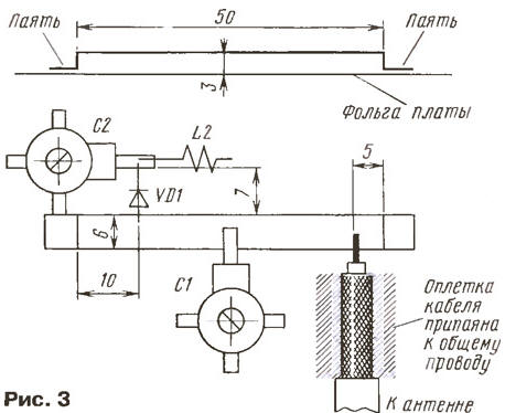
Mounting is carried out by a hinged method on the terminals of the elements, also using several mounting platforms cut out with a sharp knife. You can also apply the well-known technology for manufacturing mounting platforms, once proposed by S. Zhutyaev (RW3BP). Stator terminals of tuned capacitors are used as attachment points for parts (rotary terminals are soldered to the board foil, which ensures rigid fastening of the capacitors). It should not be forgotten that on the microwave the length of the connecting wires and leads of the installed parts should be minimal. At these frequencies, even 5 mm is already a very long conductor. This is especially true for the conclusions of the mixing diode VD1, the length of which should be minimal. When soldering the diode, it is necessary to use a heat sink and it is desirable to use low-temperature solder. The converter uses tuned capacitors KPK-MP, constants - KD, KT or KM. It is desirable to use a leadless capacitor C4, such as K10-42. Capacitor Csv - two pieces of PEV-2 wire with a diameter of 1 mm and a length of 15 mm, located at a distance of 1 mm from each other. It is advisable to put a fluoroplastic tube on one of them to avoid short circuits. It is convenient to use reference capacitors as blocking capacitors C5, C8, C13, C19, which will reduce the required number of cut out mounting sites, since the conclusions of these capacitors can be used as them. All resistors - MLT-0,25. Transistors can be replaced with KT316, KT325 with any letter. The line of the input resonator L1 is made of a strip of copper foil 6 mm wide and 62 mm long. A U-shaped bracket 50 mm long and 3 mm high with 3 mm slopes is bent (see the upper part of Fig. 3), which is then soldered to the board. The thickness of the copper foil is not essential, as long as it provides sufficient mechanical strength to the structure (0,2 mm is enough). In the center of the line, the stator terminal of the tuning capacitor C1 is soldered. The terminals of the capacitor rotor are soldered to the "common wire" (lower part of Fig. 3).
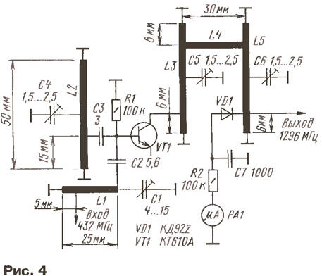
Inductors L2-L8 are frameless, wound with bare copper wire with a diameter of 0,8 mm. Coils L2, L5 have 2 turns wound on a mandrel with a diameter of 4 mm, the length of the winding is 7 mm. Coils L3, L4 - 7 turns each, wound on a mandrel with a diameter of 6 mm, winding length - 14 mm. Retraction at L4 from the third from the left according to the coil scheme. Coils L6, L7 - 4,5 turns each, wound on a mandrel with a diameter of 6 mm, winding length - 10 mm. Retraction at L7 from the 1st turn, counting from the "hot" end. Coil L8 has 6 turns wound on a mandrel with a diameter of 6 mm, winding length - 18 mm. Branch at L8 from the top according to the scheme of the 2nd turn. The input of the converter is connected to the RF connector with a small piece of coaxial cable suitable for structural reasons. The cable braid must be soldered to the common wire of the board (without unraveling it) in the immediate vicinity of the entry point. It is better to use a cable with fluoroplastic insulation, which does not melt when soldering. It is convenient to use the input connector of the "cable" type, for example, СР-50-1, CP-50-163. If you use a "device" type connector, then it is necessary to connect the cable sheath to the connector body, directly near the connector insulator, with several strips of foil of the shortest possible length. The rest of the design of the converter has no features. Setting up the converter comes down to setting the circuits to the specified frequencies and setting the operating current through the mixer diode. To do this, at the setup stage, in series with the resistor R1, it is necessary to turn on a milliammeter with a full deviation current of 1 mA. The fact that the desired harmonics are selected in the loops of the local oscillator multipliers and that the master oscillator operates at the desired frequency is desirable to control using a suitable receiver. It must be remembered that when changing the mode of the mixing diode, the input resonator and the last local oscillator circuit are somewhat detuned due to a change in the capacitance of the diode. Therefore, when changing the auto-bias resistor of the diode, it is necessary to adjust the circuits. As an input signal at the first stage of tuning, the author used the signals of base stations of the GSM-900 system, which operate at a frequency of 960 MHz, tuning the input resonator to the mirror channel. With a tuning capacitor C1, the input resonator is tuned in the range of approximately 800 ... 1500 MHz. When using quartz at 63,5 MHz, GSM-900 signals (characteristic buzz of digital transmission) are heard when the receiver is tuned to a frequency of (approximately!) (3 x 381) - 960 = 183 MHz. Also, these signals are listened to at a frequency of 960 - (2 x 381) = 198 MHz (conversion at the second harmonic of the local oscillator). You should choose the conversion at the working third harmonic of the local oscillator (the maxima of the conversion efficiency at different harmonics of the local oscillator correspond to slightly different settings). After that, it remains only to rebuild the input resonator to the operating frequency (here you will need a signal with an amateur band frequency), adjust the output circuit of the converter to an intermediate frequency with the capacitor C6 and slightly refine the setting of the L2C2C4 circuit. Multiplier 432/1296 MHz A simple frequency multiplier 432/1296 MHz, the circuit of which is shown in fig. 4, in combination with a transmitter operating in the range of 430 ... 433 MHz, allows you to receive a signal in the range of 1290 ... 1299 MHz.
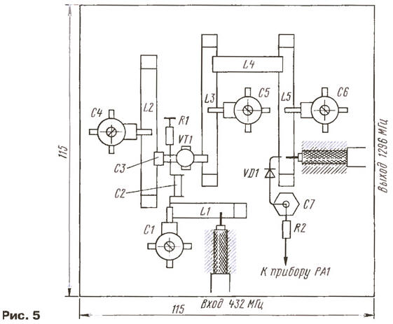
The base-collector junction of the KT610A transistor is used as a varactor in the design. The KT913A transistor was also tested, which made it possible to obtain more power. The choice of a transistor as a varactor is due to its convenient design, which makes it possible to use a serial multiplier circuit. The emitter leads of the transistor are not used and must be cut off in close proximity to the body of the transistor. As shown by the experiments and theoretical calculations, in order to obtain sufficient efficiency of the generation of the third harmonic, it is necessary to introduce the so-called "idle circuit" into the circuit, tuned to the second harmonic of the input signal. This "idle circuit" is marked on the diagram as L2C4 and is switched on at the input of the varactor. At the output of the multiplier, two coupled resonators L3C5L4L5C6 are used, which makes it possible to obtain a low level of spurious radiation. The design of the resonators (both output and idle) are identical to those used in the converter. Recall that such a resonator can be tuned in the range of 800 ... 1500 MHz with a tuning capacitor and therefore the "idle circuit" is identical in design to the output, although it is tuned to a different harmonic of the input signal. In the case when it is not possible to set the "idle circuit" to 864 MHz, you can slightly increase the capacitance of the capacitor C3. The L1C1 input resonator, tuned to 432 MHz, is a "half" resonator at 1296 MHz, and, in addition, it uses a larger tuned capacitor. The multiplier is mounted on a plate of foil fiberglass (a copper sheet can also be used). The arrangement of parts is shown in fig. 5. The required structural dimensions of the resonators and the points of connection of elements to them are shown in fig. 4. Features of connecting the input and output coaxial cables and comments on connectors, as in the first part of the article.
To adjust the multiplier, it is desirable to have a suitable selective microvoltmeter or at least a scanner. First of all, the input resonator L1C1 is tuned to a frequency of 432 MHz, then the "idle circuit" L2C4 is tuned to the second harmonic - 864 MHz. To do this, it is necessary to apply a signal with a frequency of 432 MHz with a power of 1 ... 2 W to the input of the multiplier and, taking the second harmonic signal to the scanner, adjust the capacitors C1 and C4 according to the maximum level of the received signal. The scanner antenna will most likely need to be disabled. In the future, when tuning the output resonators L3C5 and L5C6, it is necessary to adjust C1 and C4 several times, since the settings affect each other The adjustment of the output resonators with capacitors C5 and C6 must be carried out according to the maximum readings of the output indicator PA1, a microammeter with a total deflection current of 200 μA. It should not be forgotten that the tuning range of the resonators with tuning capacitors is quite large, and it is possible to erroneously tune the output resonators to the second harmonic instead of the third. Usually, tuning to the second harmonic is obtained with the capacitance of the tuning capacitor close to the maximum, and to the third - approximately in the middle position of the capacitor rotor. In addition, the tuning of the resonators is somewhat dependent on the level of the input signal. Therefore, when changing the transmitter power to 432 MHz, it is necessary to refine the setting. With the correct setting of the multiplier, its efficiency should be 50 ... 70%. Therefore, by bringing a signal with a power of about 5 W to it, for example, at a frequency of 432 MHz, you can get a power of 2,5 ... 3,5 W at a frequency of 1296 MHz. Author: A. Yurkov (RA9MB), Omsk
A New Way to Control and Manipulate Optical Signals
05.05.2024 Primium Seneca keyboard
05.05.2024 The world's tallest astronomical observatory opened
04.05.2024
▪ Concept self-driving car Mitsubishi Electric EMIRAI 4 ▪ Memories warm both the soul and the body ▪ Computer mouse without borders
▪ section of the site Aphorisms of famous people. Article selection ▪ article Lathe. History of invention and production ▪ Is it possible to prove paternity by blood type? Detailed answer ▪ article Explorer. Standard instruction on labor protection ▪ article Wind as a source of energy. Encyclopedia of radio electronics and electrical engineering ▪ article Video sync pulse regenerators. Encyclopedia of radio electronics and electrical engineering
Home page | Library | Articles | Website map | Site Reviews
www.diagram.com.ua |


 Leave your comment on this article: