|
|


 Arabic
 Bengali
 Chinese
 English
 French
 German
 Hebrew
 Hindi
Hindi Italian
 Japanese
 Korean
 Malay
Malay Polish
 Portuguese
 Spanish
 Turkish
 Ukrainian
 Vietnamese
|
ENCYCLOPEDIA OF RADIO ELECTRONICS AND ELECTRICAL ENGINEERING Digital AFC for the transceiver. Encyclopedia of radio electronics and electrical engineering
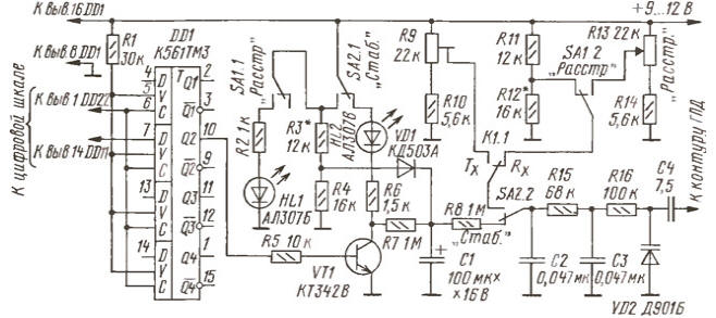
Encyclopedia of radio electronics and electrical engineering / Civil radio communications The method for stabilizing the local oscillator frequency using a digital scale-frequency meter has been known for a long time and has been repeatedly described in periodicals, for example, in [1, 2]. Taking as a basis a digital auto-tuning device (DAFC) from [2], the author developed a frequency stabilization unit and control of the GPA detuning using a digital scale from the "CONTEST" transceiver [3]. The digital scale is made according to the well-known scheme of V. Krinitsky (RA9CJL) [4] with modifications described in [5]. Schematic diagram of the digital AFC node in the stabilization mode is shown in the figure.
At input D (pin 7) of the DD1 chip (only one of the four triggers of the chip is used), a signal is supplied from the first output of the low-order counter of the TsSh (pin 14 of the DD11 chip). The numbering of the pins of the TsSH microcircuits is given according to the material published in [3]. At the input C (pin 6) DD1, a rewrite pulse from the TsSH was applied (pin 1 of the DD22 chip). To ensure the correct operation of the DD1 chip with the original signals of the digital signal, a logic unit level is applied to the input V (pin 5) through the resistor R1. The signal at the trigger output (pin 10) of the DD1 microcircuit controls the operation of the transistor switch on VT1. An integrating circuit R1, C7, R1 is connected to the collector of transistor VT8, which forms the control voltage of the varicap, which is fed to the varicap VD2.2 through the contacts of the switch SA2 and the RF decoupling filter C15R3C16R2. Power is supplied to the collector of the transistor VT1 through the contacts of the switch SA2.1, the LED HL2 and the resistor R6. LED HL2, stabilization mode indicator, during normal operation of the system should flash with a period of 4 ... 15 s. This scheme made it possible to obtain a stable frequency grid of the GPA transceiver with a resolution of 200 Hz. The operation of the above nodes is described in more detail in [2]. When the stabilization mode is turned off, the supply voltage through the contacts SA2.1 is supplied to the divider R3R4 and the contacts of the switch SA1.1 (turning on the indication of the detuning mode). From the midpoint of the divider R3R4, the voltage is supplied through the diode VD1 to the integrating capacitor C1. This is necessary to charge the capacitor C1 with the stabilization mode turned off to a level at which the GPA frequency remains unchanged after the stabilization mode is turned on. In this case, the necessary conditions will be provided for stabilizing the GPA both with an increase in its frequency and with a decrease. Diode VD1 prevents the discharge of capacitor C1 through the divider R3R4. The SA1 switch is used to turn on the detuning mode, the HL1 LED signals its inclusion. Detuning control is possible only when the stabilization mode is turned off and is carried out by a variable resistor R13. K1.1 - contacts of the command relay of the transceiver, which serves to switch the "reception-transmission" mode. Establishing the circuit in the "Detuning" mode consists in selecting the resistor R12 so that when the detuning is turned off, the GPA frequency corresponds to the frequency with the detuning turned on and the middle position of the slider of the potentiometer R13. The tuning resistor R9 sets the coincidence of the frequencies of the GPA during reception and transmission. In the "Stabilization" mode, by selecting the resistor R3, the local oscillator frequencies are matched in the stabilization mode and without it. The last operation can be controlled by the equality of constant voltages at the junction of C2 and R15. Elements C2, R15, C3, R16 should be located in close proximity to the GPA circuit. Literature
Author: V.Rubtsov (UN7BV), Astana, Kazakhstan
The world's tallest astronomical observatory opened
04.05.2024 Controlling objects using air currents
04.05.2024 Purebred dogs get sick no more often than purebred dogs
03.05.2024
▪ Multi-mode wireless technology for sensor networks ▪ Scotland's wind farms are overworking ▪ Happiness from altruism is short-lived ▪ Giant Natural Particle Accelerators
▪ section of the website Audiotechnics. Article selection ▪ article Not to have a place to lay your head. Popular expression ▪ article How did Hewlett and Packard choose a name for their company? Detailed answer ▪ article Toolmaker. Job description ▪ article Lady of the day. Focus Secret
Home page | Library | Articles | Website map | Site Reviews
www.diagram.com.ua |

 Leave your comment on this article: