|
|
ENCYCLOPEDIA OF RADIO ELECTRONICS AND ELECTRICAL ENGINEERING Radio station Len - at 29 MHz FM. Encyclopedia of radio electronics and electrical engineering
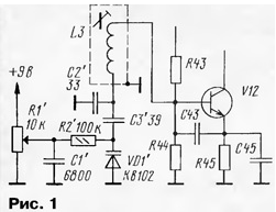
Encyclopedia of radio electronics and electrical engineering / Civil radio communications Often, radio amateurs use industrial communication equipment for their own purposes, subjecting it to the necessary alteration. One of the options for using such equipment for amateur communications with the FM in the ten-meter range is described in the proposed article. The industry produces a wide range of radio stations "Len" ("Len-V", "Len-M", "Len-B"), which differ both in design and circuitry. In this case, the radio station "Len-V" 1Р21С-3 underwent alteration. There are four options for its frequency performance: 33...39 MHz, 39...46 MHz, 46...48,5 MHz and 57...57,5 MHz. The first option (33 ... 39 MHz) is more preferable, although this is not important, any one will do - you just have to work harder with rewinding the circuits. Receiver. In the local oscillator of the receiver, a VZ channel quartz resonator is soldered (all designations according to the technical description for the 1P21S-3 "Len-V" radio station, except where otherwise specified), instead of it, a KB 102 varicap and additional elements are soldered according to the diagram in Fig. 1.
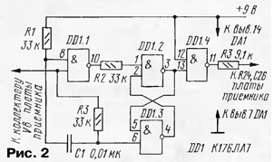
Designations of newly introduced elements are given with a stroke. The local oscillator frequency is 18,5 ... 19 MHz with the tuning range of the transceiver 29,2 ... 29,7 MHz. Circuits E9, E10, E11 are tuned to resonance with capacitors C48, C51, C52, respectively. Perhaps, in order to obtain a more uniform output voltage, it will be necessary to shunt the E9 circuit with a resistor, which is selected during the setup process. The capacitance of the capacitor C2 (Fig. 1) sets the desired tuning range, and the capacitor C3 - the necessary stretching of the range. You should not leave large margins at the edges of the range, it is enough to leave 10 ... 20 kHz each, since the simplest tuning option is used using a variable resistor R1 (an ordinary SP-1 type resistor is suitable) without a vernier. The number of turns of the GPA contour coil is 18 on a frame with a diameter of 9 mm. The coils of the circuits E9, E10, E11 contain 18 turns each with a tap from the middle, all circuits must be in screens. In UHF, the capacitances of the loop capacitors in the circuits E1, E2, E68 are 7 pF. This applies to all types of stations, since the number of turns in the UHF circuits is the same for all frequency options. UHF is tuned in any known way, the bandwidth is set by capacitor CXNUMX. The UPC does not need to be adjusted, provided that the factory seals on the coil cores are not broken. If, nevertheless, the IF is upset, then it is highly desirable to use a GSS with the possibility of frequency modulation to configure it. In place of the noise suppressor board, a digital tuning scale is installed (more on it below), the noise suppressor itself (Fig. 2) is placed in the free space of the receiver board, between the quartz filter and the A4 microcircuit. Holes are drilled in the receiver board for the K176LA7 chip and resistors, which are soldered on the reverse side using a mounting wire. As a ULF, you can use a regular ULF radio station, or you can breed it in the free space of the receiver board, next to the K174URZ chip. In this case, you can use, for example, K174UN7, K174UN14 microcircuits, setting the minimum intrinsic gain, since the gain of the K224UNZ and K224UN2 microcircuits is quite high.
Signal transmitter obtained by mixing the frequency of the GPA and the reference oscillator 10,7 MHz. The reference oscillator voltage is modulated in phase by a low-frequency audio voltage. The transmitter board is undergoing more rework. Circuits E2, E4 of the transmitter board are rewound for all versions. The circuits E5, E6, E33 for the 39 ... 8,5 MHz option are not rewound, for the other options they are also rewound. The data of these circuits is 3 turns with a tap from the 1rd turn, counting from the 68st output of the circuit (both on the diagram and on the circuit itself, all the outputs are numbered). The capacitances of the divider capacitors included in the circuits are 100 and 25 pF. The values of the contour capacitances are: C28, C24 - 32 pF, C3, C34, C36, C36 - XNUMX pF. The mixer and the local oscillator amplifier are made as separate modules (Fig. 3).
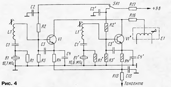
The boards for the modules are made of foil material, the pattern of the boards is very simple and is cut with a scalpel. Details are soldered from the side of the foil. The mixer board A2 is installed vertically between the circuit screen L4 and resistor R29. One end of the capacitor C22 is soldered to the transmitter board to the circuit L4 and resistor R25, and the other is soldered to the midpoint of the mixer transformer T2'. Capacitor C2' is installed in the same way - with one output to the transmitter board, to the base V7, the other - to the transformer T2' of the mixer. The local oscillator amplifier board is installed nearby. The circuits L1, L4 are rewound, they contain 33 turns. The L1 coil is used to set the reference oscillator frequency to 10,7 MHz, the L4 coil is adjusted for the best modulation quality. To be able to work in repeater mode, it is necessary to install one more reference frequency generator. Its frequency should be lower than the main one by 100 kHz, i.e. 10,6 MHz. The transmitter board provides space for two more quartz channel oscillators, holes in the board for one of them are drilled and the elements are soldered according to the main scheme. The generator switching circuit is shown in fig. 4, new elements are marked with a dash.
The switch SA1 selects the mode of operation of the transceiver, switching occurs by supplying a control voltage to the base circuits of the transistors. In the lower, according to the scheme, position, a 10,6 MHz generator works and the transmission goes 100 kHz lower relative to the receive frequency, this does not affect the receiver frequency in any way. The circuit E1 is adjusted to the maximum voltage of the generators, if necessary, the circuit capacitor C15 is selected. Circuits E2 ... E6 are adjusted to the maximum output voltage of the power amplifier. During tuning, the output of the power amplifier must be loaded on a load equivalent - a 50 Ohm resistor, with a power of 10-15 W. P-loop coils are rewound: L10 - 7 turns, L11, L12, L13, L14, L15 - 9 turns. C41 - 390 pF, C42 - 330 pF, C45 - 82 pF, C49 - 47 pF, C52 - 330 pF, C53 - 56 pF, C58 - 82 pF, C59 - 180 pF, C60 - 180 pF, C61 - 82 pF. The P-loop is tuned by compressing and stretching the turns; for the 33 ... 39 MHz option, the P-loop can be tuned without rewinding. The digital scale was taken from the book "The best designs of the 31st and 32nd exhibitions of radio amateurs" (M.: ed. DOSAAF, 1989 - p. 96). Minor changes were made to it, the first two counting decades were left, and the decade of hundreds of kilohertz was replaced by the counter K176IE2 and K176ID2 for the possibility of pre-recording. The number 176 is recorded in the K2IE7 counter, units and tens of megahertz are not counted, and the number 29 is formed by the corresponding wiring of the indicator outputs. The circuit of the quartz oscillator has been changed. In principle, it is not at all necessary to use this circuit, it is important to get a frequency of 176 Hz at the input of the K1TM100 trigger. This condition was achieved with a minimum number of chips with a 256 kHz quartz resonator. When desoldering the printed circuit board of the TsSH, you need to carefully follow the missing connections according to the circuit and tracks. This applies to the power supply of microcircuits, the outputs of microcircuits DD6, DD7, etc. The board is connected through a connector similar to the connectors of a radio station. Scheme of a modified digital scale and a sketch of its printed circuit board Author: Yu.Chinkov (RA4UBZ)
The world's tallest astronomical observatory opened
04.05.2024 Controlling objects using air currents
04.05.2024 Purebred dogs get sick no more often than purebred dogs
03.05.2024
▪ Router Netgear R6250, 802.11ac (5G Wi-Fi) ▪ Smartphone Vivo X3 thickness less than 6 mm ▪ Diet can change the taste of sugar ▪ Quiet New Fujitsu Celsius Workstations ▪ Adult elephants calm the youth
▪ section of the Garland website. Article selection ▪ article Electric motor. History of invention and production ▪ How many hours a day do you need to sleep? Detailed answer ▪ article Cat. Legends, cultivation, methods of application ▪ article Improving FM radio reception. Encyclopedia of radio electronics and electrical engineering
Home page | Library | Articles | Website map | Site Reviews www.diagram.com.ua |


 Arabic
 Bengali
 Chinese
 English
 French
 German
 Hebrew
 Hindi
Hindi Italian
 Japanese
 Korean
 Malay
Malay Polish
 Portuguese
 Spanish
 Turkish
 Ukrainian
 Vietnamese


 Leave your comment on this article: