|
|


 Arabic
 Bengali
 Chinese
 English
 French
 German
 Hebrew
 Hindi
Hindi Italian
 Japanese
 Korean
 Malay
Malay Polish
 Portuguese
 Spanish
 Turkish
 Ukrainian
 Vietnamese
|
HISTORY OF TECHNOLOGY, TECHNOLOGY, OBJECTS AROUND US
Electric motor. History of invention and production
Directory / The history of technology, technology, objects around us An electric motor is an electrical machine (electromechanical converter) in which electrical energy is converted into mechanical energy, the side effect of which is the release of heat.
The greatest technical achievement of the late XNUMXth century was the invention of the industrial electric motor. This compact, economical, convenient motor soon became one of the most important elements of production, displacing other types of motors from wherever electric current could be delivered. The big drawbacks of the old steam engine have always been low efficiency, as well as the difficulty of transferring and "crushing" the energy received from it. Usually one large machine served several dozen machines. The movement from it was brought to each workplace mechanically using pulleys and endless belts. In this case, huge unjustified losses of energy occurred. The electric drive did not have these flaws: it had a high efficiency, since rotational motion could be directly obtained from its shaft (whereas in a steam engine it was converted from reciprocating), and it was much easier to “crush” electrical energy. Losses at the same time turned out to be minimal, and labor productivity increased. In addition, with the introduction of electric motors, for the first time, it became possible not only to supply any machine with its own engine, but also to put a separate drive on each of its nodes. Electric motors appeared in the second quarter of the XNUMXth century, but several decades passed before favorable conditions were created for their widespread introduction into production. One of the first perfect electric motors powered by a DC battery was created in 1834 by the Russian electrical engineer Jacobi. This engine had two groups of U-shaped electromagnets, of which one group (four U-shaped electromagnets) was located on a fixed frame. Their pole pieces were arranged asymmetrically - elongated in one direction. The motor shaft consisted of two parallel brass disks connected by four electromagnets placed at an equal distance from one another.
When the shaft rotated, the movable electromagnets passed against the poles of the fixed ones. In the latter, the polarities went alternately: either positive or negative. To the electromagnets of the rotating disk departed conductors mounted on the shaft of the machine. A commutator was mounted on the motor shaft, which changed the direction of the current in moving electromagnets during each quarter of the shaft revolution. The windings of all electromagnets of the fixed frame were connected in series and flowed around the battery current in one direction. The windings of the electromagnets of the rotating disk were also connected in series, but the direction of the current in them changed eight times per revolution of the shaft. Consequently, the polarity of these electromagnets also changed eight times in one revolution of the shaft, and these electromagnets were alternately attracted and repelled by the electromagnets of the fixed frame.
Let us suppose that the movable electromagnets occupy a position in which opposite each pole of the fixed magnets stands the same pole of the movable one; at the same time, each stationary electromagnet will repel the opposite magnet of the drum and attract the nearby one with the opposite pole. If the poles of the fixed magnets were not asymmetrical, such a device could not work, since the action of the various magnets would balance each other. But due to the protrusion of the pole pieces of the fixed magnets, each of them attracts the nearest clockwise rotation weaker than the other, because of this, the first approaches it, and the last moves away. After a quarter of a turn (in the Jacobi engine - after one eighth), opposite poles will be opposite one another, but at this moment the commutator changes the direction of the current in the moving magnets, and one will again have the same poles opposite the other, as at the beginning of the movement. As a result of this, the moving magnets again receive a push in the same direction, and so on without end, as long as the current remains closed. The commutator was a very important and deeply thought-out part of the engine. It consisted of four metal rings mounted on the shaft and isolated from it; each ring had four notches that corresponded to 1/8 of the circumference. The cutouts were filled with insulating wooden liners; each ring was offset 45 degrees from the previous one. A lever, which was a kind of brush, slid along the circumference of the ring; the other end of the lever was immersed in a suitable vessel with mercury, to which conductors from the battery were connected (mercury compounds were the most common contact devices at that time). Disks mounted on the motor shaft rotated with it. Metal levers slid along the rim of the disc, which, falling on the non-conductive part of the disc, interrupted the electrical circuit, and when in contact with the metal, closed it. The arrangement of the disks was such that at the moment when the opposite poles met, the contact levers passed through the wood-metal face and thereby changed the direction in the winding of the electromagnets. Thus, with each turn of the ring, the electrical circuit was broken four times. As already noted, the Jacobi engine for its time was the most advanced electrical device. In the same year, 1834, a detailed report on the principles of his work was presented to the Paris Academy of Sciences. In 1838, Jacobi improved his electric motor and, having installed it on a rowing boat, with ten satellites made a small voyage along the Neva at a speed of 4 km / h. A powerful battery of galvanic cells served as a current source. It is clear, however, that all these experiments were purely demonstrative in nature - until a perfect electric generator was invented and put into production, electric motors could not be widely used, since it was too expensive and unprofitable to power them from a battery. In addition, for various reasons, which we will discuss in the following chapters, DC motors have received only limited use. A much more important role in production is played by electric motors operating on alternating current, to which we now turn. The strength and direction of alternating current, as we remember, are not constant. Its strength first increases from zero to some maximum value and again decreases to zero, then the current changes its direction, increases to some negative maximum and again decreases to zero. (The time it takes for the current to change from one positive maximum to another is called the current oscillation period.) This process is repeated at high frequency. (For example, in a lighting network, current flows fifty times in one direction and fifty times in the opposite direction in 1 second.) How will this behavior of the current affect the operation of the electric motor? First of all, it should be noted that the direction of rotation of the electric motor does not depend on the direction of the current, because when the current changes, the polarity will change not only in the armature, but simultaneously in the windings, which is why attraction and repulsion continue to act in the same direction as before. It seems to follow from this that it makes absolutely no difference to the engine what kind of direct or alternating current - it is powered. However, it is not. With frequent magnetization reversal of electromagnets (several tens of times per second), eddy currents arise in them, which slow down the rotation of the armature and heat it up greatly. The power of the electric motor is sharply reduced, and eventually it fails. For alternating current, a special motor design is required. The inventors were not immediately able to find it. First of all, a model of the so-called synchronous AC motor was developed. One of the first such engines was built in 1841 by Charles Wheatstone. Suppose that the fixed part of the engine (stator) is made in the form of an eight-pole crown-shaped electromagnet, the alternate poles of which are designated by their polarity by the letters N and S. An armature (or rotor) rotates between them in the form of a star-shaped wheel, eight spokes of which are permanent magnets. Their fixed poles will be denoted by the letters n and s. Assume that an alternating current is passed through an electromagnet. Then the ends of the cores of the electromagnet will alternately change their polarity. Imagine that at some point opposite each pole of the stator electromagnet there is a rotor pole of the same name. Let us push the wheel and tell it such a speed at which each spoke n will cover the distance between two adjacent cores N and S in a time interval equal to that during which these cores keep their polarity unchanged, that is, in a period of time equal to half the period of the alternating current that feeds the electromagnets. Under such conditions, during the entire movement of the spoke from the core N to the core S, all the cores will be remagnetized, which is why, with its further movement, the spoke will again experience repulsion from the core left behind, and attraction from the core to which it approaches.
The synchronous motor operating on this principle consisted of a ring-shaped multi-pole magnet, the polarity of which changed under the influence of alternating current, and a star-shaped permanent electromagnet, which was mounted on a shaft and rotated in the manner described above. To excite this permanent electromagnet, a direct current was required, which was converted by means of a commutator from a working variable. The commutator had another purpose: it was used to start the engine, because in order to maintain the rotation of the rotor of a synchronous motor, it needed to report a certain initial speed. When turned on, a direct current was first started through the circuit, due to which the motor began to work as a DC motor and set in motion. Until the engine reached the required speed, the commutator reversed direction in the moving electromagnets. When the speed corresponding to the synchronous stroke was reached, the poles of the moving magnet did not change anymore, and the motor began to work as a synchronous AC motor.
The described system had major drawbacks, in addition to the fact that the synchronous motor required an additional accelerating motor for its launch, it also had another flaw - when overloaded, the synchronism of its stroke was disturbed, the magnets began to slow down the rotation of the shaft, and the motor stopped. Therefore, synchronous motors are not widely used. The real revolution in electrical engineering took place only after the invention of the asynchronous (or induction) motor. The action of an induction motor will be clear from the following demonstration, which was carried out in 1824 by the famous French physicist Argo.
Let the horseshoe magnet NS be driven by hand into rapid rotation about the vertical axis. Above the poles there is a glass plate supporting the point, on which a copper circle is mounted. When the magnet rotates, the induction currents induced in the circle and the magnetic field formed by them will interact with the bottom magnet, and the circle will begin to rotate in the same direction as the bottom magnet. This phenomenon is used in an asynchronous motor. Only instead of a rotating permanent magnet, it uses several stationary electromagnets that turn on, turn off and change their polarity in a certain sequence. Let us explain what has been said with the following example.
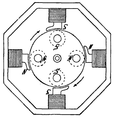
Suppose that I, II, III and IV are the four poles of two electromagnets, between which a metal arrow is placed. Under the action of a magnetic field, it is magnetized and becomes along the lines of the magnetic field of electromagnets, which, as you know, leave their north pole and enter the south. All four poles are located in a circle at the same distance from each other. First, current is applied to II and III. The arrow remains motionless along the middle axis of the magnetic field lines. Then current is supplied to the second electromagnet. In this case, the poles of the same name will be nearby. Now the average guide of the lines of force of the magnets will pass from the middle of the distance between I and II to the middle between III and IV, and the arrow will turn 45 degrees. We turn off the first electromagnet and leave only poles II and IV active. The lines of force will be directed from III to IV, as a result of which the arrow will turn another 45 degrees. We turn on the first electromagnet again, but at the same time we change the movement of the current, so that the polarity of the first magnet will change - the arrow will turn another 45 degrees. After turning off the second electromagnet, the arrow will move another 45 degrees, that is, it will make a half turn. It's easy to see how to get her to complete the second half of the circle. The device described by us basically corresponds to the Bailey engine, invented in 1879. Bailey made two electromagnets with four crosswise poles, which he could magnetize with a switch. Above the poles, he installed a copper circle suspended on a point. By changing the polarities of the magnet, turning them on and off, he made the circle rotate in exactly the same way as it happened in Argo's experiment. The idea of such a motor is extremely interesting, since, unlike DC motors or synchronous electric motors, there is no need to supply current to the rotor. However, in the form in which Bailey created it, the induction motor could not yet be used: the switching of electromagnets in it occurred under the action of a complex collector, and, in addition, it had a very low efficiency. But before this type of electric motor gained the right to life, only a step remained, and it was made after the advent of the technique of polyphase currents. Actually, multiphase currents have been used, primarily due to electric motors.
To understand what, for example, a two-phase current is, imagine two conductors independent of each other, in which two completely identical alternating currents flow. The only difference between them is that they do not reach their maximums at the same time. They say about such currents that they are phase-shifted relative to each other, and if these currents are supplied to one electrical appliance, they say that it is powered by a two-phase current. Accordingly, there can be a three-phase current (if the device is powered by three identical currents shifted relative to each other in phase), a four-phase current, etc. For a long time, only conventional alternating current was used in technology (which, by analogy with multi-phase currents, began to be called single-phase). But then it turned out that in some cases multi-phase currents are much more convenient than single-phase ones.
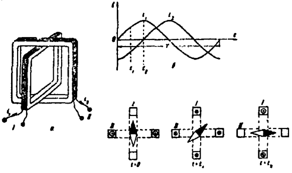
In 1888, the Italian physicist Ferraris and the Yugoslav inventor Tesla (who worked in the USA) discovered the phenomenon of a rotating electromagnetic field. Its essence was as follows. Take two coils, consisting of the same number of turns of insulated wire, and place them mutually perpendicular so that one coil enters the other. Now imagine that current i1 flows around coil 1 and current i2 flows around coil 2, with i1 leading i2 in phase by a quarter of a period. This, as we have already said, means that the current i1 reaches a positive maximum at the moment when the current i2 is zero. If we mentally cut the coils in half with a horizontal plane and look at them from above, we will see sections of the four sides of both coils. Let us place a magnetic needle between them and observe its movement. Coils through which alternating current flows are known to be electromagnets. Their magnetic field will interact with the needle, turning it. Consider now the position of the magnetic needle, the axis of which coincides with the vertical axis of the coils at different times. At the initial moment of time (t=0), the current in the first coil is zero, and in the second it passes through a negative maximum (the direction of the current will be denoted as it is done in electrical engineering - with a dot and a cross; a cross means that the current is directed from the observer beyond the plane drawing, and the dot indicates that the current is directed towards the observer). At time t1, the currents i1 and i2 are equal to each other, but one has a positive direction and the other has a negative direction. At the moment t2, the value of the current i2 goes down to zero, and the current i1 reaches its maximum. The arrow will then turn another 1/8 turn. Tracing the development of the process in this way, we will notice that at the end of the period of change of one of the currents, the magnetic needle will complete a complete revolution around the axis. Then the process is repeated. Therefore, with two coils fed with two currents out of phase with respect to each other by a quarter of a period, you can get the same effect of reversing the magnetic poles that Bailey achieved in his motor, but here it is much simpler, without any commutator and without using sliding contacts, since the current itself controls the magnetization reversal. The described effect has received in electrical engineering the name of a uniformly rotating magnetic field. Based on it, Tesla designed the first two-phase asynchronous motor in history. In general, he was the first who began to experiment with polyphase currents and successfully solved the problem of generating such currents. Since it was not easy to get a two-phase current from a single-phase one, Tesla built a special generator that immediately produced two currents with a phase difference of 90 degrees (that is, a quarter of a period behind). In this generator, two mutually perpendicular coils rotated between the poles of a magnet. At the time when the turns of one coil were under the poles and the current induced in them was maximum, the turns of the other coil were between the poles (on the neutral line) and the electromotive force in them was equal to zero. Consequently, the two currents generated in these coils were also out of phase with respect to each other by a quarter of a period.
Three-phase current could be obtained in a similar way (using three coils at 60 degrees to each other), but Tesla considered the two-phase system to be the most economical. Indeed, multi-phase current systems require a large number of wires. If a motor operating on conventional alternating (single-phase) current requires only two supply wires, then operating on a two-phase one - already four, on a three-phase one - six, etc. The ends of each coil were brought to the rings located on the generator shaft. The motor rotor also had a winding in the form of two coils closed on themselves (that is, having no connection with an external electrical circuit) located at right angles to each other. Tesla's invention marked the beginning of a new era in electrical engineering and aroused the liveliest interest throughout the world. Already in June 1888, the Westinghouse Electric Company bought all the patents for a two-phase system from him for a million dollars and offered to organize the production of asynchronous motors at their factories. These engines went on sale the following year. They were much better and more reliable than all the models that existed before, but they were not widely used, as they turned out to be very unsuccessfully designed. The stator winding in them was made in the form of coils mounted on protruding poles. The design of the rotor in the form of a drum with two mutually perpendicular, closed coils was also unsuccessful. All this significantly reduced the quality of the engine both at the time of start-up and in operating mode. Soon, Tesla's induction motor was significantly redesigned and improved by the Russian electrical engineer Dolivo-Dobrovolsky. Expelled in 1881 for political reasons from the Riga Polytechnic Institute, Dolivo-Dobrovolsky left for Germany. Here he graduated from the Darmstadt Higher Technical School and in 1887 began working in the large German electrical engineering company AEG. The first important innovation that Dolivo-Dobrovolsky introduced in an asynchronous motor was the creation of a rotor with a "squirrel cage" winding. In all early models of induction motors, the rotors were very unsuccessful, and therefore the efficiency of these motors was lower than that of other types of electric motors. (Ferraris, mentioned above, created an asynchronous two-phase motor with an efficiency of about 50% and considered this to be the limit.) The material from which the rotor was made played a very important role here, since it had to satisfy two conditions at once: to have low electrical resistance (in order to induced currents could freely flow through its surface) and have good magnetic permeability (so that the energy of the magnetic field is not wasted).
From the point of view of reducing electrical resistance, the best design solution could be a rotor in the form of a copper cylinder. But copper is a poor conductor for the stator magnetic flux and the efficiency of such a motor was very low. If the copper cylinder was replaced with a steel one, then the magnetic flux increased sharply, but, since the electrical conductivity of steel was less than that of copper, the efficiency was again low. Dolivo-Dobrovolsky found a way out of this contradiction: he made the rotor in the form of a steel cylinder (which reduced its magnetic resistance), and began to insert copper rods into the channels drilled along the periphery of the latter (which reduced the electrical resistance). On the frontal parts of the rotor, these rods were electrically connected to each other (closed on themselves). Dolivo-Dobrovolsky's solution turned out to be the best. After he received a patent for his rotor in 1889, his device did not fundamentally change until the present. Following that, Dolivo-Dobrovolsky began to think about the design of the stator of the fixed part of the engine. Tesla's design seemed irrational to him. Since the efficiency of an electric motor directly depends on how fully the stator magnetic field is used by the rotor, then, therefore, the more stator magnetic lines are closed to air (that is, they do not pass through the surface of the rotor), the greater the loss of electrical energy and the less efficiency. To prevent this from happening, the gap between the rotor and the stator should be as small as possible. Tesla's engine from this point of view was far from perfect - the protruding poles of the coils on the stator created too much clearance between the stator and the rotor. In addition, in a two-phase motor, a uniform movement of the rotor was not obtained. Proceeding from this, Dolivo-Dobrovolsky saw two tasks before him: to increase the efficiency of the engine and to achieve greater uniformity of its operation. The first task was simple - it was enough to remove the protruding poles of the electromagnets and evenly distribute their windings around the entire circumference of the stator so that the efficiency of the engine immediately increased. But how to solve the second problem? The unevenness of rotation could be noticeably reduced only by increasing the number of phases from two to three. But was this path rational? Getting a three-phase current, as already mentioned, was not difficult. It was also not difficult to build a three-phase motor - for this it was enough to place three coils on the stator instead of two and connect each of them with two wires to the corresponding generator coil. This motor was supposed to be better than Tesla's two-phase motor in all respects, except for one moment - it required six wires for its power supply, instead of four. Thus, the system became unnecessarily bulky and expensive. But maybe it was possible to connect the engine to the generator in some other way? Dolivo-Dobrovolsky spent sleepless nights over diagrams of multi-phase circuits. On sheets of paper, he sketched more and more new options. And, finally, a solution, completely unexpected and ingenious in its simplicity, was found.
Indeed, if you make branches from three points of the ring armature of the generator and connect them to three rings along which the brushes slide, then when the armature rotates between the poles, the same current will be induced on each brush, but with a shift in time, which is necessary so that the coil moves along an arc corresponding to an angle of 120 degrees. In other words, the currents in the circuit will also be shifted relative to each other in phase by 120 degrees. But this three-phase current system turned out to have one more extremely curious property that no other system of multi-phase currents had - at any arbitrarily taken moment of time, the sum of the currents flowing in one direction is equal here to the value of the third current that flows in the opposite direction, and the sum of all three currents at any time is zero. For example, at time t1, current i2 passes through a positive maximum, and the values of currents i1 and i3, which have a negative value, reach half the maximum and their sum is equal to current i2. This means that at any given time one of the wires in the system is carrying the same amount of current in one direction as the other two together are carrying in the opposite direction. Therefore, it is possible to use each of the three wires as a lead wire for the other two connected in parallel, and instead of six wires, get by with just three!
To clarify this extremely important point, let us turn to an imaginary diagram. Imagine that through a circle rotating around its center, there are three conductors connected to each other, in which three alternating currents flow, shifted in phase by 120 degrees. During its rotation, each conductor is either on the positive or on the negative part of the circle, and when moving from one part to another, the current changes its direction. This system fully ensures the normal flow (circulation) of currents. Indeed, at some point in time, conductors I and II are connected in parallel, and III diverts current from them. Some time later, II goes over to the same side as III; now II and III work in parallel, and I as a common current-carrying wire. Then III passes to the side where I is still located; now II withdraws the amount that III and I bring together. Then I moves to the side where II is still located, and so on.
In the above example, nothing was said about current sources. As we remember, this source is a three-phase generator. We represent the windings of the generator in the form of three coils. In order for the current to flow in the manner we have described, these coils can be included in the circuit in two ways. We can, for example, place them on three sides of a triangle, say the left one; thus, instead of its three sides, we get three coils I, II and III, in which currents are induced with a phase shift of 1/3 of the period. We can also move the application points of electromotive forces to the ends of the parallel conductors. If we put our coils here, we get a different connection. The triangles, now serving only as conductive connections for the three left ends of the coils, can be contracted to a single point. These connections, of which the first is called "delta" and the second - "star", are widely used in both engines and generators.
Dolivo-Dobrovolsky built his first three-phase asynchronous motor in the winter of 1889. As a stator, an annular anchor of a DC machine with 24 half-closed slots was used in it. Given Tesla's mistakes, Dolivo-Dobrovolsky dispersed the windings in the slots around the entire circumference of the stator, which made the distribution of the magnetic field more favorable. The rotor was cylindrical with "squirrel cage" windings. The air gap between the rotor and the stator was only 1 mm, which at that time was a bold decision, since usually the gap was made larger. The rods of the "squirrel cage" had no insulation. A standard DC generator was used as a three-phase current source, rebuilt into a three-phase generator as described above. The impression made by the first start of the engine on the leadership of the AEG was enormous. For many, it became obvious that the long thorny path of creating an industrial electric motor was finally completed. In terms of their technical performance, Dolivo-Dobrovolsky's engines surpassed all electric motors that existed at that time - having a very high efficiency, they worked flawlessly in all modes, were reliable and easy to use. Therefore, they immediately became widespread throughout the world. Since that time, the rapid introduction of electric motors in all areas of production and the widespread electrification of industry began. Author: Ryzhov K.V.
Artificial leather for touch emulation
15.04.2024 Petgugu Global cat litter
15.04.2024 The attractiveness of caring men
14.04.2024
▪ Canon M-i1 Android Projector ▪ Mijia Smart Electric Kettle 5L
▪ section of the site Amateur Radio Technologies. Selection of articles ▪ article by Gabrielle Sidonie Colette. Famous aphorisms ▪ article How can macaques cooperatively move objects with their minds? Detailed answer ▪ article Small nasturtium. Legends, cultivation, methods of application
Home page | Library | Articles | Website map | Site Reviews
www.diagram.com.ua |


 See other articles Section