|
|


 Arabic
 Bengali
 Chinese
 English
 French
 German
 Hebrew
 Hindi
Hindi Italian
 Japanese
 Korean
 Malay
Malay Polish
 Portuguese
 Spanish
 Turkish
 Ukrainian
 Vietnamese
|
ENCYCLOPEDIA OF RADIO ELECTRONICS AND ELECTRICAL ENGINEERING Universal VHF-UHF receiver SEC-850M. Encyclopedia of radio electronics and electrical engineering
Encyclopedia of radio electronics and electrical engineering / radio reception A modern broadcasting receiver, even with an analog form of signal processing, but with digital methods of controlling adjustments and calling functionality, is more and more gravitating towards some kind of computing device. No handles, toggle switches - only buttons combined into a keyboard, a convenient and multifunctional remote control, a digital display that displays information about a working radio station (frequency, name, signal level, presence of a stereo mode), a large bank of frequencies of priority stations and their direct call or keyboard dialing at a known frequency - all this, with a high quality of the reproduced sound, makes working with the receiver not only convenient, but also pleasant communication with a "smart" device. A description of such an amateur-designed receiver (and not much inferior to the industrial one from leading companies) is given in this article. The idea to assemble a survey VHF receiver was born back in 1993, when television all-wave channel selectors (SHF) with frequency synthesis appeared in the CIS. This opened up very interesting prospects, since the frequency stability of such selectors is very high and is determined only by the reference quartz resonator. From the point of view of narrow-band reception, SLE has a significant drawback - a large overlap coefficient of resonant circuits over the range (only 3 sub-bands per 800 MHz). This does not characterize its selective and noise characteristics in the best way, and also leads to the need to make a complex system for matching input circuits to branch the input signal into three subbands, which leads to losses. It is for these reasons that the SLE is slightly inferior in its noise parameters to the channel selectors of the meter or decimeter range, although the input amplifiers used in it, according to passport data, have a noise figure of 1,2 ... 1,4 dB. However, a large number of other advantages of SCR compensate for these shortcomings, and we decided to try this device. The first receiver on the Lithuanian "digital" selector KS-H-62 was designed to receive narrow-band FM stations of the 144 and 430 MHz amateur radio bands and tested in 1994. The control program at that time was written by our friend A. Samusenko. The receiver had very good characteristics: - continuous range from 50 to 850 MHz with a tuning step of 62,5 kHz; - selectivity on the mirror channel - not worse than 70 dB; - bandwidth for the second IF 10,7 MHz - 15 kHz; - sensitivity - about 0,5 μV; - frequency instability at room temperature - no worse than ±1 kHz per hour at a frequency of 850 MHz. The narrow-band FM detector was made on a K174XA6 chip. The main selection for 10,7 MHz IF was determined by the FP2P-307-10,7M-15 quartz filter. In the future, with the advent of new interesting broadcasting stations on VHF, the receiver was finalized. The new receiver is primarily intended for high-quality reception of broadcasting stations in the "Mono" and "Stereo" modes of various broadcasting standards and sound accompaniment of television stations in the MB and UHF bands. A 3H block appeared in the receiver, which allows receiving stereo broadcast programs with a fairly good quality. The receiver is built on a modular basis, so if necessary it can be modified for specific conditions by connecting additional submodules in the radio frequency (RF) unit. For example, to receive narrowband stations, you need to make a small submodule that can be easily connected to the main version. This will be useful for ultrashortwave radio amateurs and those involved in the repair of radiotelephones and radio stations. For large cities, in which the number of radio stations (especially in the VHF bands) already exceeds more than a dozen, it is desirable to improve the selectivity in the adjacent channel by making an additional IF filter submodule. To reduce the dimensions, this submodule is assembled on chip elements and can be installed in the module instead of a single piezoceramic filter in the RF unit. The range of received frequencies, if necessary, can be extended to 900 MHz using an imported channel selector, designed for reception in the UHF range not up to the 60th, but up to the 69th channel of the American standard. The program provides for such an option. Main Specifications
Functionality - convenient digital indication of the tuning frequency and the current levels of volume control, balance, high and low frequencies, the number of the called channel; - 4x4 keyboard (+2 additional keys) that allows direct dialing of frequency, recording and calling up 41 recorded channels, automatic search for stations up and down by frequency value, step-by-step tuning up or down; - mode "Quiet reception"; - switching modes "Narrow - wide band"; - control of audio adjustments (volume, balance, low-frequency tone, high-frequency tone, switching to an external audio input, switching audio effects: linear stereo (Linear Stereo), spatial stereo (Spatial Stereo), pseudo-stereo (Pseudo Stereo) and forced mono (Forsed Mono), as well as when switching inputs, the audio processor can operate in Stereo, Stereo A and Stereo B modes); - non-volatile memory, which stores the above audio adjustments for each channel; - indication of the level of the input RF signal (S-meter); - silent search and channel switching; - remote control with RC-5; - quiet listening (MUTE mode), while listening to on-air programs through a separate amplifier for stereo phones and all audio adjustments are provided, and the final stage of the UZCH is closed. Functional diagram The receiver consists of four main modules (Fig. 1).
The RF module (A1) contains an all-wave channel selector. The device performs double frequency conversion, frequency detection and amplification of the received 3H voltage or complex stereo signal (CSS). The same module includes a 5/31 V voltage converter, silent tuning devices, AGC and an S-meter. Submodules of narrowband reception (A1.3) and additional filter (A1.2) can be connected to the module. The 3H (A2) module performs stereo signal decoding, preamplification, bass and treble tone control, switching of stereo effects, 3H power amplification and allows you to listen to programs through stereo phones, connect an external signal source to the receiver amplifier, connect speakers with an impedance of 4 to 8 ohms to a power amplifier. The module has three voltage stabilizers needed to power the rest of the receiver units. The control module (A3) incorporates a microcontroller that forms the l2C control bus, an 8-bit dynamic display, and a keyboard. The current settings are stored in non-volatile EEPROM separately for each memory location. All basic adjustments can be made from a remote control with RC-5 protocol (you can use industrial devices from TVs of the Vityaz, Horizont models of the 4th and 5th generations, etc.). The A4 power module generates the 16 V voltage required to power the entire receiver. The maximum load current is up to 4,5 A. RF module (A1) Schematic diagram of the RF module is shown in fig. 2.
The device is made according to the superheterodyne circuit with double (with narrow-band reception - with triple) frequency conversion. The first conversion is carried out by a small-sized channel selector A1.1 - "5002РН5" (Temic), it is possible to use similar devices "KS-H-132" (Selteka) or "SK-V-362 D" (PO "Vityaz", Belarus), which include a frequency synthesizer. The channel selector is controlled by the 12C bus formed by the control unit. The SAW filter of the first IF 10ZQ11 of the UFPZP1-1 type with a center frequency located in the range from 7 to 5.48 MHz (in our receiver it is 31,5 MHz) and a bandwidth of -38 dB of about 31,7 kHz is connected to the symmetrical output of the selector (pins 3 and 800). Similar filters are used in televisions with a parallel sound channel. The filter output is matched by the 1L1 coil, which creates an oscillatory circuit with the filter output capacitance tuned to resonance at the operating frequency. This makes it possible to reduce the losses in the filter to 3...4 dB and narrow the bandwidth for the first IF to 500...600 kHz. Instead of a SAW filter, a three-circuit FSS can be used - with coupling coils on the first and last circuits. In this case, the dimensions will only increase. The output impedance of the selector is purely active and is equal to 100 ohms. You can try to use here a conventional filter with a frequency of 38 MHz on a SAW with a "double-humped" frequency response, which is used in the radio channels of modern TVs, but due to the fact that the bandwidth for the first IF in this case will be about 7 MHz, noise will probably increase and the selectivity in the adjacent channel will drop. After the first IF filter, a frequency converter on a 1DA1 chip follows, at the output of which there is a second IF filter - 10,7 MHz, made on one 1ZQ2 piezoceramic filter and matched by the 1L3, 1L4, 1C9 circuit. The local oscillator of the 1DA1 microcircuit is stabilized by a 1BQ1 quartz resonator with a frequency of 21 MHz, the 1L2 coil serves to fine-tune the frequency of the quartz resonator. The filtered signal of the second IF is fed to the 1DA2 chip, which further amplifies, limits and detects FM signals. Elements 1L7, 1C21 - the contour of the quadrature FM detector. In parallel, the IF signal is started on the AGC, BSHN, S-meter circuits, assembled on 1VT2-1VT6 transistors. Similar internal circuits of the K174XA6 microcircuit are not used in this case, since due to the high level of the input signal coming to its input, they work inefficiently. The transistor device has a greater dynamic range and performs better. The filtered IF signal is amplified by a resonant cascade on a 1VT2 transistor, then fed to a logarithmic detector made on a 1VT4 transistor and a 1VD4 diode. At low signal levels, the input impedance of the stage is high due to the high resistance of the closed diode 1VD4 in the 1VT4 emitter circuit. The cascade works like a line detector. With an increase in the signal level, the 1VD4 diode begins to open, the input resistance of the cascade drops and shunts the input signal. From this point on, the cascade begins to work as a logarithmic detector. The characteristic of the detector can be changed by the base bias of the 1VT4 transistor and the selection of the 1VD4 diode. The rectified voltage is integrated on the 1R20,1C38 chain and the input resistance of the emitter follower on the 1VT5 transistor. The voltage, which decreases with an increase in the input signal, from the output of the 1VT5 emitter follower through dividers to 1R25 and 1R28, respectively, is supplied to pin 1 of the channel selector (AGC) and to the key stages on transistors 1VT6 and 1VT3. They perform a double inversion of the control voltage and its approximation to the logic signal used to control the squelch and stop the autoscan. The complex stereo signal from pin 7 of the 1DA2 chip is fed to the 1DA4 operational amplifier. The amplifier amplifies the CSS to a level of 300...600 mV, which is necessary for the normal operation of the stereo decoder. On the printed circuit board of the RF unit (A1) (Fig. 3), on the printing side, using CHIP elements, a 5/31 V converter is made on a 1VT1 transistor.
The converter is a self-oscillator with an operating frequency of about 400 kHz. This device is distinguished by its simplicity, the absence of home-made winding products (the used coils 1L5 and 1L6 with an inductance of 1000 μH are normalized RF chokes with a low level of radiation, produced by many companies and widely available for sale). The main task of this converter is to obtain a voltage that is 1 ... 2 V more than the frequency synthesizer requires at a given tuning point. Therefore, at a frequency of 850 MHz, the voltage at the selector input will be about 33 V, and at a frequency of 50 MHz it may be 5 ... 7 V due to the increased load. This must be taken into account when setting up the converter. It is best to check it without a selector at idle. The open circuit voltage should be within 35 ... .40 V. If there is no desire to assemble a converter, then a separate winding on a transformer with a rectifier and a stabilizer on a KS531 V zener diode is perfect. On the circuit diagram of the RF block (A1) there is a 1DD1 chip of the PCF8583 type. This is a clock controlled via the l2C bus, but, unfortunately, in this version of the receiver design, the microcircuit is not yet involved. There is a place for 1DD1 on the printed circuit board. In the future, we plan to use it, and this will not require any design improvements. Used elements Coils of inductance. 1L1 - 25 turns of PEV-2 0,25 wire on a frame with a diameter of 5 mm with a carbonyl iron trimmer or an RF choke with an inductance of 2,2 μH (for filters used by the authors). As coils 1L3 and 1L4, a connected TOKO circuit with a built-in capacitor or a similar one with a lilac or orange color marking was used. Such coils can be purchased at radio markets or soldered from any broken Chinese-made "soap box". Such coils can be made independently. On a four-section standard polystyrene frame with a screen used in 4th and 5th generation TVs, it is necessary to wind 24 and 4 turns, respectively, with PEV-2 0,25 wire. Coil turns 1L4 should be placed in one of the sections on top of coil turns 1L3. The 1L7 coil with a built-in capacitor is used by the same named company, it has a green or pink marking. When self-manufacturing, it should be made in the same way as the 1L3 coil. Coils 1L2 and 1L8 - high-frequency chokes type EC24-3R9K, inductance - 3,9 μH, tolerance - + 10%. As a 1L2 coil, you can use the same as 1L1. Coils 1L5 and 1L6 are high-frequency chokes of the EC24-102K type, inductance - 1000 μH, tolerance - ± 10%. Resonators and filters. Resonator 1BQ1 - frequency 21 MHz, 1BQ2 - 32768 Hz (clock). The requirements for the 1ZQ1 filter are described above. The 1ZQ2 filter is a small-sized piezoceramic filter for a frequency of 10,7 MHz (for example, type L10.7MA5 from TOKO). Semiconductor devices. All diodes - series KD521, KD522. Transistor 1VT1 - KT315, transistors 1VT3, 1VT4, 1VT6 - KT3102, transistor 1VT5 - KT3107. All diodes and bipolar transistors with any letter index. Transistor 1VT2 - KP303B, KPZ0ZG, KPZ0ZE, KP307B, KP307G. Resistors. All constants - C1-4 0,125 or MLT-0,125, trimmers - SPZ-386. Capacitors. Oxide - K50-53 with an operating voltage of 6,3 and 10 V, the rest - K10-176 of the M47 group. Connectors. Intermodular connectors - XS1, XS2 type OWF-8. Channel selector A1.1. Various modifications of the selectors may differ from each other in the exchange protocol over the l2C bus, depending on the type of frequency synthesizer chip used. Selectors with TSA552x series chips (Philips) can be used in this receiver, allowing you to select the division ratio of the reference divider. We are interested in a step of 50 kHz and the transmission ratio of the reference divider Ko = 640. This allows the above-mentioned devices to be done without changing the proposed program. They use a frequency synthesizer type TSA5522. There are some others (almost all selectors from Temic, Philips with TSA5520 and TSA5526 microcircuits), but for them you will have to adjust the control program for a different 1C exchange protocol. You can generally abandon the five-volt selector and use a twelve-volt one. According to the exchange protocol on the 12C bus, selectors such as "KS-H-92 OL" (Selteca), "SK-V-164 D" (PO Vityaz) are suitable. In this case, the AGC system will also have to be abandoned, since with these selectors the AGC must be nine-volt. The pinout and dimensions of these selectors also differ from the five-volt version. The sensitivity and selectivity of the receiver will not change. Additional filter submodule (A1.2). If in your area you can receive more than 7 - 10 stations in the broadcasting range of 88 ... 108 MHz, then in order to increase the selectivity in the adjacent channel, the printed circuit board provides for the installation of a more complex IF filter on two piezoceramic filters (Fig. 4).
The voltage transfer coefficient of the A1.2 block from point 1 to point 2 must be 0,7 ... 1 and is determined by an aperiodic amplifier made on DA1 S595N (TR) (Temic). The gain of the cascade should compensate for the losses in the ZQ1ZQ2 filters and it can be selected by the resistor R1. It makes no sense to make the block gain greater than 1, since after the channel selector, which has a gain of at least 40 dB, and K174PS1 - 20 dB, the signal voltage of the second IF will be at the level of units and tens of millivolts, which is more than enough. The filter with a compensating amplifier is made on CHIP elements and assembled on a separate board, which is installed perpendicular to the main board instead of a single 1ZQ2 filter (points 1, 2, 3). +5 V power supply is brought to this board by a hinged mounting conductor from a jumper located nearby on the RF unit (point 4).
Used elements Semiconductor devices. Amplifier DA1 type S595T (this amplifier is a microcircuit consisting of a double-gate field-effect transistor with internal bias circuits along the first gate and source) is widely used in the input circuits of modern channel selectors, can be replaced by S593T, S594T, S886T, BF1105 (Philips). Filters. ZQ1, ZQ2 - small-sized piezoceramic filters with a frequency of 10,7 MHz - (for example, L10.7MA5 from TOKO). Coil L1 - high-frequency choke type EC24-3R9K, inductance - 3,9 μH. You can use any CHIP or MY coil (for example, with an inductance from 2,2 to 4,7 μH, produced by Monolit, Vitebsk) to reduce the size of the submodule. Narrowband reception submodule (A1.3). The radio receiver allows you to receive stations with narrow-band FM. To do this, you need to make a narrowband reception submodule. The schematic diagram of the submodule is shown in fig. 6.
The narrowband receiver on the DA1 chip has no features and is assembled according to a typical scheme, repeatedly described in the literature. It allows you to receive high-quality radio stations with a frequency deviation from 1 to 5 kHz. This block is made on a separate printed circuit board (Fig. 7) and may not be manufactured.
Switching SHP - UE is carried out by the processor of the control unit when the 3SA1 button is pressed or from the remote control. This turns on the 3VD1 LED, the processor signal with a log level. 0 (point 9 of module A3) opens the transistor VT1 of the submodule, which, in turn, controls the relay K1. The input of the operational amplifier 1DA4 (see Fig. 2) through the normally open contacts of relay K1 receives an audio signal from the submodule microcircuit. When connecting this unit, you need to remove the jumper L on the RF unit. On the printed circuit board, this jumper is made in the form of a gap on the printed conductor between pin 7 of the 1DA2 chip and the 1C36 capacitor and is easily installed with a drop of solder during soldering (removed by removing the solder). If possible, use a short coaxial cable to connect point 9 of the RF unit to point 8 of the submodule. Further passage of the low-frequency signal through the stereo decoder does not affect the signal quality in any way. Narrowband stations can also be received on the main version of the receiver without making a special submodule. To do this, you need to increase the resistor 1R8 to 10 kOhm (remembering to reduce it when receiving broadcasting stations) in module A1. This resistor allows you to change the slope of the discriminator characteristic, so you can get a higher level of low-frequency signal with a small deviation. In this case, you need to put up with the poor performance of the squelch due to the low levels of the RF signal of narrow-band stations and the low level of the low-frequency signal. Resistor R6 sets the noise suppressor threshold. If the frequency tuning step of 50 kHz is insufficient, then a smooth tuning of ± 25 kHz can be introduced in the submodule by removing the BQ1 quartz resonator at 10,235 MHz, capacitor C4 and applying a signal from a separate smooth generator with a level of 1 ... 1 mV and a frequency of 100 to 200 kHz to pin 10210 of the DA10260 chip. Substitutions The MC3361C chip can be replaced with KA3361, with a change in the circuit and printed circuit board - with K174XA26, MC3359, MC3371, MC3362. Transistor VT1 - KT3107, KT209 with any letter index. Filter ZQ1 - piezoceramic frequency 465 kHz. Any domestic or imported from broadcasting receivers will do. BQ1 - quartz resonator with a frequency of 10,235 MHz. Coil L1 - a standard coil with a built-in capacitor C12 from TOKO with a yellow marking or similar, tuned to a frequency of 465 kHz. Module 3H (A2) The complex stereo signal (CSS) from the frequency detector of the RF module (A1) through pin 8 of the XP2 connector of the 3Ch module enters the stereo decoder, made on the 2DA1 LA3375 microcircuit of the LF block (Fig. 8).
Initially, a cheaper stereo decoder chip of the TA7343P type was used in the device, but it did not stand up to criticism - the cascades following it were overloaded with a powerful subcarrier with a frequency of 19 kHz (pilot tone). The influence manifested itself only when receiving stations with stereo mode and on the oscilloscope the amplitude of the pilot tone signal was 3 (!) times greater than the useful signal. Only the LA3375 chip completely solved this problem. The scheme of its inclusion is typical. The output of the microcircuit can additionally be used as a line output of the receiver. Further, the low-frequency separated signal of the left and right channels is fed to the 2DA2 TDA8425 (Philips) audio processor, where the necessary amplification, frequency correction and audio signal adjustment take place. Then the 3H signal is fed to the 2DA6 power amplifier with a 2R17, 2C43, 2C45 delay chain, which allows silent channel switching. In the receiver, the MUTE mode is simultaneously turned on both in the final UZCH and via the I2C bus in the audio processor. At the same time, a weak click will be heard in stereo phones when switching channels due to the fact that the MUTE mode of the audio process. The 2DA5 chip has an amplifier for operating low-impedance stereo phones connected to the XS5 output connector. The module has an additional linear low-frequency input (XS4) and can be used as a conventional power amplifier with convenient service. In this case, you can turn on the mode in which the signal from one input channel (left or right) goes to two channels of the amplifier at once. Stabilizers on 2DA4, 2DA7 microcircuits allow you to get rid of processor interference and dynamic indication as much as possible and serve to power the digital and analog parts of the device, respectively.
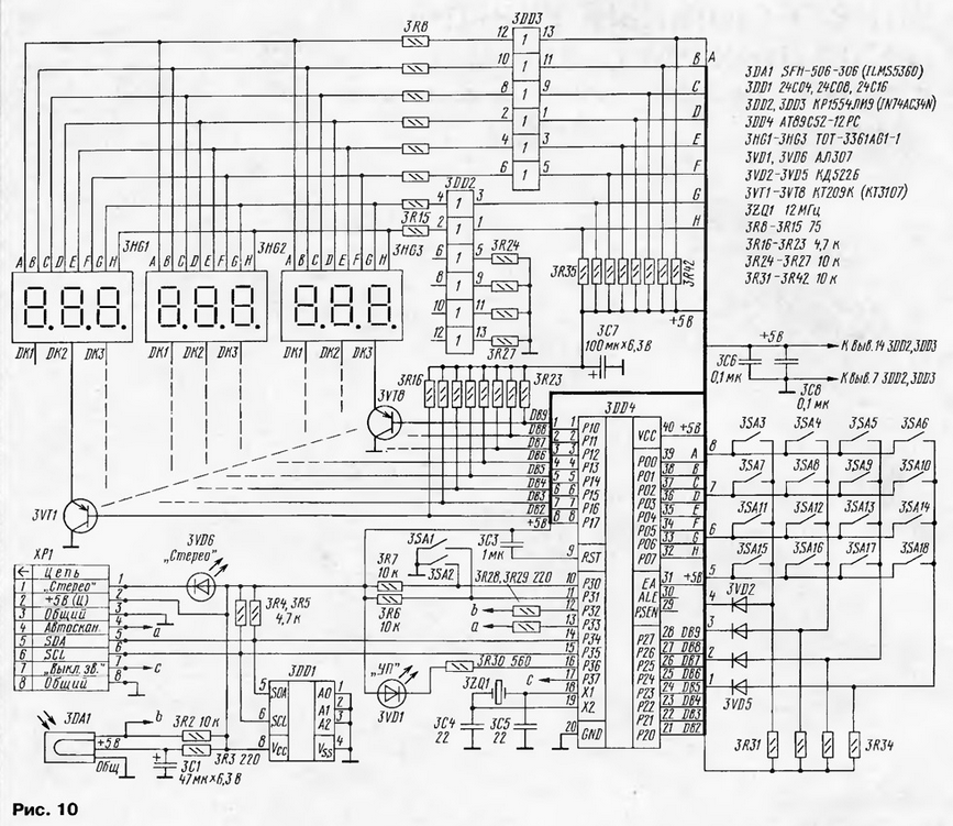
Used elements Semiconductor devices. Transistor 2VT1 - KT3102 with any letter index. Instead of the 2DA6 microcircuit of the bridge ultrasonic frequency converter TDA1552Q, you can use similar ones - TDA1553Q, TDA1557Q, by connecting a capacitor with a capacity of 12 microfarads and an operating voltage of 100 V to their terminals 16. There is a place for its installation on the printed circuit board. Microcircuit stabilizer 2DA3 and 2DA4 - KR142EN5 or KR1157EN5A. Fixed resistors - C1-4 0,125 or MLT-0,125, variables - SPZ-386. Capacitors: K10-17, oxide - K50-53. Control module(A3) The control module (Fig. 10) is based on a 3DD4 AT89S52-12RS microcontroller with an internal ROM of 8 kb and generates control signals via the I2C bus to control the 1A1 channel selector (RF module), the 2DA2 audio processor (3Ch module), and the 3DD1 non-volatile ROM (hereinafter also single-chip clocks).
The control unit has a 4x4 3SA3-3SA18 keyboard plus two additional buttons 3SA1, 3SA2, a nine-digit display of three LED indicators 3HG1 - 3HG3 of the TOT3361AG type (only 8 digits are used), LEDs 3VD6 - "Stepeo", 3VD1 - "Narrow band", photodetector 3DA1. Powerful repeaters 3DD2, 3DD3 type KR1554LI9 serve to increase the load capacity of the RO processor port. When "quiet reception" is turned on, the dynamic indication, which serves as a source of interference, is turned off. When the "Narrow band" mode is enabled, the 3VD1 LED turns on, the control signal from the same output of the microcontroller goes to the narrowband reception submodule and the 3H outputs of the K174XA6 and MC3361 microcircuits are switched. The printed circuit board of the module and the arrangement of elements on it are shown in fig. eleven.
The module does not require any configuration and, if properly installed, works immediately. It is only necessary to memorize the current settings - more on that below. Microcontroller firmware codes in HEX format Used elements Semiconductor devices. Transistors 3VT1 - 3VT8 series KT3107, KT209. LEDs 3VD1, 3VD6 - AL307, 3VD2 - 3VD5 - KD521, KD522. These transistors and diodes can be taken with any letter index. Chips 3DD2 - 3DD3 - KR1554LI9, IN74AC34N; 3DD1 - 24C04 or any non-volatile EEPROM with a capacity of 1 kb, controlled via the I2C bus; integrated photodetector 3DA1 - SFH-506 (you can use any TV from the 5th - 6th generation or imported, for example, ILMS5360); microcontroller 3DD4 - AT89S52-12RS or any of this family with 8 kb memory. Switches 3SA1-3SA18 push-buttons PKN-159 or T8-A1P8-130. Resonator 3ZQ1 with a frequency of 10 to 12 MHz of any type. Resistors - C1-4 0,125 or MLT-0,125, SPZ-386. Capacitors - K10-176, K50-53. Power module (A4) This power supply is made according to a single-cycle scheme and provides the power necessary for the operation of the receiver nodes and a minimum of interference radiation. The obtained parameters of the power source: load current - 4 A; voltage - 16 V. Voltage instability with a pulse current load of 4A - no more than 0,1 V. Emission of interference, even in close proximity to the receiver and without shielding, was not detected either at low frequency or at the operating frequencies of the receiver. The interference spectrum is concentrated in the region of 8...9 MHz with a level of about 500 μV at a distance of 0,5 cm from the pulse transformer. A schematic diagram of the power supply is shown in Fig.12.
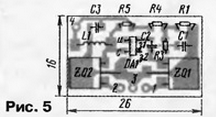
The control is performed on a very common and cheap 4DA2 chip of the UC3844 or UC3842 type. The key element is the 4VT1 MOSFET (BUZ 90, KP707G, IRFBC40). Current feedback is removed from the source 4VT1. The output voltage is controlled by a parallel-type stabilizer 4DA3 TL431 (KR142EN19). Voltage feedback with decoupling of the primary and secondary circuits is performed through an optocoupler 4DA1 AOT128A (4N35). The rectifier of the secondary circuit is made on a double Schottky diode 4VD8 KDS638A. The 4VT1 transistor and the 4VD8 diode are mounted on a common L-shaped heat sink using mica spacers. The horizontal part of the radiator is located above the power module board. The 4T1 power filter transformer is made on a K20x12x6 M3000NMS ferrite ring magnetic core, and 4T2 is made on an imported Epcos magnetic core with a frame and consists of three parts (purchased in a store, its description is given in the Radio magazine, 2001, No. 11, pp. 47, 48): B66358-G-X167, fer rit N67 ETD29EPCS (2 halves with a gap in the central core of 0,5 mm); B66359-A2000, ETD29EPCS transformer brace; B66359-B1013-T1, ETD29EPCS transformer frame. The 4T1 transformer has two windings of 20 turns each, made with PEV-2 0,7 wire. To improve electrical safety, they should be placed on opposite sides of the magnetic circuit, previously wrapped with two or three layers of insulating lavsan film. Winding data of the 4T2 transformer: winding 3-13 is wound in 2 layers of 34 turns, evenly laid along the entire length of the frame, PEV wire 2-0,4; 1-12 and 4-5 are stacked between winding layers 3-13. Winding 1-12 has 9 turns of PEV 2-0,4 wire, laid evenly along the entire length of the frame. Winding 4-5 is wound in two wires and contains 10 turns of PEV 2-0,63 wire laid evenly along the entire length of the frame. Structurally, the power supply consists of two printed circuit boards - a control board (A4.1, Fig. 13) and a power board (A4.2, Fig. 14). On the diagram, the points of their connection are indicated by respectively numbered points. For example, 1-1'. To reduce the size, both boards are located on racks one above the other (if the height of the 4C9 capacitor allows).
The feedback voltage from the output of the power supply to the control circuits 4R19-4R21, 4DA2 is supplied with a short shielded wire. The power supply has no other features and, with proper assembly, starts working immediately. Structurally, the receiver is made on four main and two additional printed circuit boards in accordance with the breakdown into modules according to the circuit diagram. The case was not specially developed, since not everyone is satisfied with a switching power supply. For a linear power supply with a power of about 70 W, a different case is needed. One of the options for the front panel of the receiver with dimensions is shown in fig. 15.
The channel selector is soldered to the PCB at four corners. When mounting the receiver in a housing, great attention should be paid to the wiring of additional "grounds" between the nodes. The presence or absence of LF interference from dynamic indication will depend on this. It is desirable to make signal wires between blocks short and shielded. The power supply can be used in any design for 16 V with a maximum current of about 4 A. RECEIVER SETUP To tune the receiver, the authors used the following devices: a G4-176 high-frequency generator, a GZ-112 audio frequency generator, an S1-99 (S1-120) oscilloscope, an X1-48 frequency response meter, and an HP ESA-L1500A spectrum analyzer. RF module (A1) Without soldering the outputs of the channel selector to the board, you need to connect one of the filter inputs to a common wire, and apply an FM signal with a frequency of 31,7 MHz with an amplitude of 50 mV and a deviation of 50 kHz to the second one. Apply 8 ... 9 V power to the input of the 1DA3 stabilizer. With an oscilloscope, monitor the signal at pin 18 of the 1DA2 chip. The coils 1L1 and 1L3 need to be used to achieve the maximum signal amplitude at the input of the K174XA6 microcircuit. Depending on the 1IF filter used, the 1L1 coil can be replaced with a coil without a trimmer with an inductance from 1,5 to 3,9 μH (according to maximum resonance) of the same type as 1L2, 1L5, 1L6, 1L8. An additional sign of inaccurate contour tuning can be the appearance of AM modulation of the RF signal, which is clearly visible on the oscilloscope with a slower sweep. The oscilloscope probe must be connected to the connection point of the 1C3З capacitor with the 1R13 resistor and achieve a maximum signal swing of 10,7 MHz at this point by adjusting the 1C31 capacitor. Using an oscilloscope, check the output of the KCC on pin 8 of the XS2 connector. The LF signal must have a correct sinusoidal shape. You can achieve an undistorted form of the low-frequency signal by adjusting the 1L7 discriminator coil, while using an oscilloscope with a closed input, you need to control the signal at pin 7 of the 1DA2 chip. With an oscilloscope, check the signal on the collector of the transistor 1VT1 of the 5/31 V converter. If the cascade is operational, there should be a sinusoid on the collector with a frequency of about 400 kHz and a swing of 15 ... 20 V. If there is no generation, it is likely that there is a break in one of the coils 1L5, 1L6 or one of the chip capacitors is broken. It is also possible that one of the capacitors is out of specification. After that, you can connect the channel selector and apply a signal with an amplitude of 50 mV, a frequency of 100 MHz to its high-frequency input. Frequency deviation - 50 kHz. Using a high-resistance voltmeter or oscilloscope, check the voltage at pin 1 of the selector (AGC voltage). With a trimmer resistor 1R25, a voltage of 3,5 ... 4 V should be set without an input signal, and with an input signal of 50 mV, the voltage should drop to 1,5 ... 2 V. If the voltage is not set below 2,5 V, you need to achieve a greater amplitude of 10,7 MHz at the drain of the 1VT2 transistor by tuning 1C31 or replacing the 1VT2 transistor with a transistor with a greater slope. In rare cases, the selection of a 1R15 resistor is required. Then you should reduce the voltage from the high-frequency generator to 10 ... 15 μV. With a 1R28 tuning resistor, it is necessary to achieve a clear operation of the BSHN system when the RF signal is turned on and off. The same trimming resistor automatically sets the threshold for stopping the scan. Scanning stops when a carrier appears, typically 2-3 steps from the broadcaster's center frequency. In this regard, fine tuning to broadcasting stations is done manually. The 1R21 trimmer can be used to calibrate the S-meter in user-friendly units. For example, on a 9-point scale adopted by radio amateurs on short waves (since this receiver is close in sensitivity to shortwave, and not to VHF equipment). Then the value of 9 points +60 dB can be taken as the maximum signal level, which corresponds to a voltage at the selector input of 50 mV (if a collective TV antenna is used, such levels are quite possible). A value of 9 + 40 dB will correspond to an input voltage of 5 mV, 9 + 20 dB - 500 μV, 9 points - 50 μV, 8 points - 25 μV, and so on up to 6. Less than 5 points should not be calibrated, since this is already at the sensitivity threshold of the AGC system. You can see the end-to-end frequency response of the receiver by applying a signal from the MFC of the frequency response meter X1-48 at a frequency of 100 MHz to the selector input. Set the meter marks to 1 + 0,1 MHz. Using the RF detector head, monitor the signal at pin 18 of the 1DA2 chip. The frequency response should have a regular bell-shaped shape without kinks and protrusions (permissibly double-humped with a dip of no more than 2 ... 3 dB) centered at a frequency of 100 MHz. The frequency response should not change shape at input signal levels from -60 to -30 dB. The shape of the frequency response can be slightly corrected with the coil trimmers 1L1 and 1L3. If you cannot achieve the required parameters, you need to choose piezoceramic filters 4ZQ1, 4ZQ2 from the same batch. In the case of installing a single 1ZQ2 piezo filter, the requirements for it are simplified. Coil 1L2 allows you to accurately set the frequency of 21 MHz. The printed circuit board provides for the option of installing both a standard choke (3,9 μH) and a coil with a trimmer, made according to the same data as 1L1. This is necessary for correct channel tuning if a narrowband unit is used. To obtain the exact frequency of the control voltage generators of the channel selector, it is desirable to accurately set the frequency of the reference oscillator to 4 MHz of its frequency synthesizer. The reference oscillator is best tuned in narrowband reception mode, at the highest operating frequency of the channel selector - 850 MHz. When tuning the receiver to this frequency, the difference between the actual tuning frequency of the VCO is ± 30 ... 40 kHz. The signal level from the G4-176 generator is about 50 μV, the frequency deviation is 5 kHz. Carefully unsolder or remove the upper and lower covers of the selector and find the quartz resonator. From the print side, identify the chip capacitor connected in series with the resonator. When setting up, it is necessary to select this capacitor with a capacitance ranging from 18 to 22 pF (with similar chip capacitors of 1 ... 2 pF, soldering them in parallel to the main one), and at the same time adjust the frequency of the RF generator until you achieve "getting into the channel". With narrowband reception, it is well audible. Then, knowing the frequency of the RF generator, determine how to further change the frequency of the reference generator. If you can use a spectrum analyzer, everything is simplified. You need to "see" the VCO frequency and set it by selecting capacitors with an accuracy of +1 kHz. This work is best done with a soldering iron with a tip diameter of about 2 mm. In this way, it is possible to achieve a detuning of no more than 500 Hz on a carrier of 850 MHz, which is quite enough. If there is no experience with chip elements, it is better not to do this work, but to accept the fact that the frequency on the indicator may differ slightly from the real one (at frequencies up to 200 MHz, no more than 2 ... 3 kHz - depends on the RMS). In this case, you can make a smooth 10,235 MHz oscillator, which compensates for the frequency mismatch and allows you to receive stations that do not fall into the 50 kHz tuning step. Additional filter submodule (A1.2). This submodule does not need to be configured. When installed in the receiver, it is enough to make sure that it works correctly. This can be done with an oscilloscope or frequency response meter. If the 10,7 MHz IF voltage is approximately the same at the input and output of the submodule, the device is working. The shape of the frequency response can be corrected by adjusting the oscillatory circuit 1L3,1L4,1C9 in the RF module. Narrowband reception submodule (A1.3). This submodule is configured prior to installation in the receiver. At the input (point 8), you need to apply an FM signal with a frequency of 465 kHz, a deviation of 3 kHz, an amplitude of 10 μV. The whole setting consists in adjusting the L1 coil until the maximum amplitude of the low-frequency signal is obtained at the output of the submodule (pin 14 DA1). Then, as part of the receiver, you need to set the noise suppressor threshold with resistor R6. To do this, apply to the receiver input a signal from a generator with a frequency of 145 MHz, an amplitude of 20 μV, a deviation of 3 kHz, and turn on / off the output voltage of the generator to determine the stable operation of the noise suppressor when an input signal of about 0,5 ... 1 μV is applied. Module 3H (A2). In this module, only the stereo decoder needs to be configured. In the absence of a stereo modulator, the stereo decoder was tuned to a radio station signal. Tune the receiver to a stereo station in the 88...108 MHz band. Turn the 2R12 trimmer slider to turn on the 3VD6 "STEREO" LED on the control board. Place the resistor in the middle of the capture zone. Set the oscilloscope probe to any of the outputs of the stereo telephones of the 3H block, and use the trimmer resistor 2R3 to achieve the greatest subcarrier suppression of 19 kHz on the oscillogram. This can be done without an oscilloscope - by ear. A sharp disappearance of distortion will indicate the correct setting. Then select a radio station on the range with a better stereo signal and a 2R1 trimmer to achieve maximum channel separation, which subjectively looks like an increase in the depth of the stereo base. We recommend that you tune the stereo decoder by ear using good stereo phones. Control module (A3). The device does not need to be configured. I would only like to share the experience of using integrated photodetectors. Often among them there are specimens that spontaneously generate single pulses. When using them in TVs, this defect does not manifest itself in any way, and in this design, the indicators may flicker in response to each pulse. When the photodetector is replaced with a high-quality one, all unpleasant effects disappear. This parasitic generation is easily detected by an oscilloscope. Power module (A4). As the practice of executing several instances has shown, with serviceable elements, this module does not require configuration. OPERATION WITH THE RECEIVER The receiver keypad has 18 buttons with conventional numbers from 18 to 16 (their conventional location, corresponding to the location on the front panel, is shown in Fig. XNUMX).
The functional purpose of the buttons: 1 - while dialing the frequency and channel number for recording - number 1, in operating mode - adjusting the stereo balance (bL). 2 - while dialing the frequency and channel number for recording - number 2, in operating mode - adjusting the "+" stereo balance (bL). 3 - while dialing the frequency and channel number for recording - number 3, in operating mode - adjusting the "-" volume (VOL). 4 - while dialing the frequency and channel number for recording - number 4, in operating mode - adjusting the "+" volume (VOL). 5 - while dialing the frequency and channel number for recording - number 5, in operating mode - adjusting the "-" treble tone (Hi). 6 - while dialing the frequency and channel number for recording - number 6, in operating mode - adjusting the "+" treble tone (Hi), 7 - while dialing the frequency and channel number for recording - number 7, in operating mode - adjusting the "-" bass tone (LO). 8 - while dialing the frequency and channel number for recording - number 8, in operating mode - adjusting the "+" timbre of the bass (LO). 9 - while dialing the frequency and channel number for recording - number 9, in operating mode - switching line input / receiver. You can switch a mono signal from any channel to two channels (Stereo, Stereo A, Stereo B). 10 - while dialing the frequency and channel number for recording - the number 0, in the operating mode - the choice of stereo effects (LIN STEREO - normal stereo, SPATIAL STEREO - theater effect, PS STEREO - pseudo stereo, FORCE MONO - mono for two channels.) 11 - button "H" - turns on the frequency dialing mode. 12 - button "P" - recording the current frequency and audio adjustments for each channel. 13 - tuning 50 kHz down. 14 - tuning up 50 kHz. 15 - search through the recorded memory cells - one back. 16 - iterate over the recorded memory cells - one forward. 17 - "UP/SHP" button - turns on the narrowband reception mode. 18 - "SCAN" button - turns on the scanning mode. When the receiver is turned on, SEC850 appears. Frequency set - Press the button 11, the indicator will show "H - - - - -" - dial the frequency. - If the frequency is less than 100 MHz, you need to dial the first zero, for example, 071,50, the display will show "71,50" (the initially dialed digit "0" is not displayed). - If you make a mistake, press button 11 again and dial again. - Before memorizing, set the adjustments to the desired position so that they are also memorized for each of the recorded channels. Setting adjustments. Using buttons 1 to 10, set the adjustment values on each channel that will be called up when the receiver is turned on. Memory entry - Press button 12, the display will show: "- - 71,50". Instead of dashes, you need to enter a two-digit cell number (from 00 to 40, when dialing a channel number over 40, the channel number 40 is recorded by default), for example, "00" - this cell is called when turned on; - Received "71,50" (leading zeros are not displayed). - Alternately calling up the frequency dialing and memorization modes, write down all the frequencies of the radio stations that interest you (from 0 to 40). - After writing all the settings, the receiver must be turned off and on again to reinitialize the EEPROM. - You can delete the frequency from the memory by writing the number 0 to all digits in this cell, while the receiver is completely software reinitialized. Scan mode - Press button 18 on the display, "- SCAN -" will appear. - Press button 13 or 14 depending on which way you want to search - up or down in frequency. - You can exit the scanning mode by pressing button 18 again. Note. The scanning mode is optional, so it is performed according to the simplest algorithm - carrier search. To fine-tune to broadcast stations, use buttons 13 and 14. Narrowband reception mode. This mode is activated by pressing the button 17 or the corresponding "AV" button on the remote control. This turns on the 3VD6 LED on the control module. By pressing the button 17 again, the receiver returns to the broadband reception mode. Working with the remote control. The program was written for the remote control-7 buttons from the Vityaz TVs, but the main functions will work on any remote control with the RC-5 protocol. The functional purpose of the buttons. - Buttons "0 - 9" call up the corresponding number of the recorded memory cell. - Button "OK" - selection of adjustments: volume Authors: V.Sazonik, V.Ermagkevich, K.Kozlov, Vitebsk, Belarus
Artificial leather for touch emulation
15.04.2024 Petgugu Global cat litter
15.04.2024 The attractiveness of caring men
14.04.2024
▪ HLG-320H-C - 320W LED driver with current stabilization ▪ Playing with other children affects language learning
▪ section of the site Biographies of great scientists. Article selection ▪ The Volga flows into the Caspian Sea. Popular expression ▪ article Providing first aid for bleeding ▪ article Ejector power plant. Encyclopedia of radio electronics and electrical engineering ▪ article Handkerchief and disappearing money. Focus Secret
Home page | Library | Articles | Website map | Site Reviews
www.diagram.com.ua |


 Leave your comment on this article: