|
|


 Arabic
 Bengali
 Chinese
 English
 French
 German
 Hebrew
 Hindi
Hindi Italian
 Japanese
 Korean
 Malay
Malay Polish
 Portuguese
 Spanish
 Turkish
 Ukrainian
 Vietnamese
|
ENCYCLOPEDIA OF RADIO ELECTRONICS AND ELECTRICAL ENGINEERING Two designs for VHF radios. Encyclopedia of radio electronics and electrical engineering
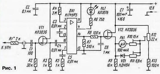
Encyclopedia of radio electronics and electrical engineering / Civil radio communications S-METER FOR "LIGHTHOUSE" This S-meter was developed for the Mayak radio station, which, in a converted form, is used by many radio amateurs to conduct communications on the 2-meter band. High sensitivity and good frequency properties allow it to be used in any VHF FM radio station. S-meter for CB radio stations, which was described in the article by Yu. Vinogradov "Switch S-meter for CB radio stations" ("Radio", 1999, No. 6, p. 65). provides a relatively small range of indicated voltage and has a low sensitivity (10 mV at a frequency of 465 kHz). For this reason, it has to be turned on closer to the final stages of the IF path, which narrows the range of measured values of the IF signal. In addition, sensitivity decreases with increasing IF, and this practically excludes the use of an S-meter in VHF FM radio stations with an IF from 10,7 to 24 MHz. The scheme of the S-meter is shown in fig. 1. The basis of the device is the DA1 chip (K174UR5). It is used in the submodule of the radio channel of third-generation TVs and is inexpensive. As you know, this microcircuit contains amplifying stages of the IF (38 MHz), nodes of the AGC system, as well as a demodulator and nodes of the AFC system. Its advantages include a high gain and a wide range of operating frequencies (up to 40 MHz).
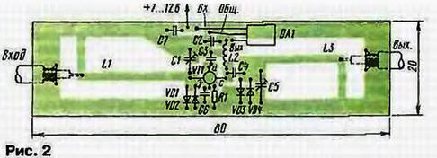
To eliminate the possible influence of the S-meter on the cascades of the radio station, a source follower on a field-effect transistor VT1 is installed at its input. On the field-effect transistor VT2, a DC voltmeter with a PA1 measuring head is assembled. With an increase in the input signal level of the IF, the constant voltage at pin 14 of the microcircuit will decrease and the arrow of the device will deviate. Diode VD1 and resistor R11 are used to expand the range of indicated voltage. In the device, two copies of the microcircuit were alternately tested. In this case, the lower limit of the indicated voltage was in the range of 30...70 μV. and the upper one - 50 ... 150mV (measurement range - 60 ... 65 dB). The indicated levels correspond to the range of the input voltage of the K174URZ microcircuit. on which the FM detector of the Mayak radio station was built. Therefore, it is more convenient to turn on such an S-meter in this case in parallel with the input of this microcircuit. On the diagram of the radio station, this point is designated "KTZ". LED HL1 provides an indication of the maximum level of the received signal. It starts to glow when the input signal level is 250...400 mV. i.e. 10 ... 15 dB above the limit value indicated by the pointer device. It is necessary to power the device from a stabilized power source, since the stability of the calibration depends on this. Current consumption - about 45 mA. The device can use transistors KP303A, KP303B. LED HL1 - any small-sized with a working current of 5 ... 10 mA. Diode VD1 - KD419B or another detector, or rectifier with a Schottky barrier. Capacitor C7 - K50. K52, K53, the rest are non-polar - KM, K 10-17 KD. Trimmer resistors - SPZ-19, constants - MLT, S2-33. Measuring head RA1 - with a total deflection current of 100 ... 200 μA and a loop resistance of 2 ... 3 kOhm. for example, M4247. Most parts of the device are placed on a printed circuit board made of double-sided foil fiberglass, a sketch of which is shown in Fig. 2. The second side of the board is left metallized. Holes in the board, into which the leads of parts that are not connected to a common wire are inserted, are countersunk. The common wire foil is connected in several places to the common wire on the other side of the board.
Connect the S-meter to the radio station after the main selection filter or to the cascades after it. Resistor R1 is placed on the radio board and connected to the S-meter board (capacitor C1) with a shielded wire of minimum length. The adjustment of the device begins with the setting of "zero" by the resistor R12 in the absence of an input signal. Resistor R10 sets the slope of the S-meter characteristic in the left half of the instrument scale, and R11 - in the right. By selecting the resistor R1, the minimum limit of the indicated voltage range is set. If, with an increase in the input signal from the minimum, a small current jump is observed through the RA 1 microammeter (10 ... 15 μA), then resistor R7 must be selected. After that, the setting should be repeated. The table shows the input signal levels and the corresponding values of the S scale (for VHF bands and the input impedance of the receiver is 50 Ohm).
If the sensitivity of the radio station is 0,15 μV (4 points), then this level should be assigned to the 5 μA division of the PA1 measuring head. In this case, the S-meter will indicate levels from four points to S9 + 45 dB. and the level of nine points will correspond to approximately 50 ... 60 μA, i.e. the scale is quite convenient. LOW-NOISE 430 MHz ANTENNA AMPLIFIER The amplifier circuit is shown in fig. 1. It is assembled on a low-noise gallium arsenide field-effect transistor VT1. The resonant circuits L1C1 and L3C5 at the input and output of the amplifier provide FET matching and frequency selection. The bandwidth of the amplifier is about 10 MHz, and the gain is 10 ... 14 dB. Both parameters depend on the connection points of the input and output cables. Diodes VD1 ... VD4 protect the transistor from breakdown by a powerful transmitter signal or discharges of static electricity.
The supply voltage of the field-effect transistor (+5 V) is stabilized by an integrated voltage regulator on the DA1 chip The amplifier is assembled on a printed circuit board made of double-sided foil fiberglass 1,5 mm thick, a sketch of which is shown in fig. 2. The second side is left metallized and connected along the contour with a foil to the common wire of the first side. The inductors are made in the form of printed conductors.
It is desirable to use unpackaged permanent capacitors in the device - K10-17B, KM-ZV, KM-4V, KM-5V, in extreme cases, you can use ordinary small-sized ceramic ones, shortening their leads to a minimum length. Trimmer capacitors - KT4-25; resistors - MLT, R1-4, R1-12. Choke L2 contains 10 turns and is wound with wire PEV-2 0,2 on a mandrel with a diameter of 3 mm. After mounting, the drain terminal of the transistor should be filled with a small amount of epoxy resin filled with carbonyl iron powder. This will greatly increase the stability of the amplifier. Establishment begins with setting the drain current of the field-effect transistor, corresponding to the minimum noise figure for this type of transistor (5 mA). The point of connection of the input cable is selected according to the maximum sensitivity, and the output cable - according to the maximum transmission coefficient. The input circuit is tuned to the middle frequency of the range by capacitor C1, and the output circuit by capacitor C5. If the amplifier is planned to be placed near the antenna, then it should include two relays, necessarily coaxial high-frequency ones. If the amplifier is installed in the receiving part of the radio station after the receive / transmit switch, then the diodes VD3, VD4 can be excluded. Author: I.Nechaev (UA3WIA)
The world's tallest astronomical observatory opened
04.05.2024 Controlling objects using air currents
04.05.2024 Purebred dogs get sick no more often than purebred dogs
03.05.2024
▪ Flash card 64 Mbit DataFlash from ATMEL ▪ Rheumatics and athletes - in the cold ▪ MIPI CSI-2 v2.0 specification introduced ▪ MSP-EXP432P401R IoT Development Board
▪ section of the site Palindromes. Article selection ▪ article To whom is a donut, and to whom is a hole from a donut. Popular expression ▪ article How is butter made? Detailed answer ▪ article Work on a lid-making machine such as VD-14, etc.. Typical instructions for labor protection ▪ article Acoustic light switch. Encyclopedia of radio electronics and electrical engineering ▪ article Pulsating faces. Focus Secret
Home page | Library | Articles | Website map | Site Reviews
www.diagram.com.ua |


 Leave your comment on this article: