|
|


 Arabic
 Bengali
 Chinese
 English
 French
 German
 Hebrew
 Hindi
Hindi Italian
 Japanese
 Korean
 Malay
Malay Polish
 Portuguese
 Spanish
 Turkish
 Ukrainian
 Vietnamese
|
ENCYCLOPEDIA OF RADIO ELECTRONICS AND ELECTRICAL ENGINEERING RDS - signal structure. Encyclopedia of radio electronics and electrical engineering
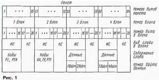
Encyclopedia of radio electronics and electrical engineering / Civil radio communications Information in the RDS system [ 1 ] is transmitted in packets consisting of four blocks of 26 bits each. The package structure is shown in fig. 1. The internal structure of the blocks is the same - each of them contains an information word (IS) 16 bits long and a control word (CS) of 10 bits, consisting of a control group (7 bits) and a shift code (3 bits).
The first block of each packet contains codes identifying the packet (radio station code PI, packet number PIN, etc.). The third and fourth blocks contain two bytes of data displayed on the receiver's display screen. The second block contains codes that determine the nature of this data. Consider the structure of the second block of the package. Let's start with the information word. The layout of information in it is shown in fig. 2.
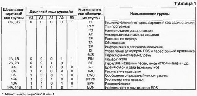
The first 6 bits are occupied by the type code of the data application group (DA) located in the third and fourth blocks of the packet. The information that can be transmitted to consumers in the RDS system is divided into 32 groups. Each contains information of a strictly defined nature. Any car or fixed RDS receiver receives all types of data packets, but the decoder of the receiver of a private person decodes and displays data on the scoreboard only for 17 groups, indicated in table. 1 compiled according to the sources [2 - 4].
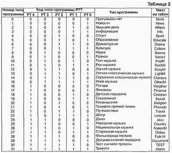
Each group has a mnemonic and numerical designation. Mnemonic (PI, RTU, etc.) consists of two to four letters and is an abbreviation of the English name (destination) of the group. It is not transmitted over the RDS channel. used only in technical documentation and literature to indicate the nature of the application of the group, and is also applied to the panel of the RDS receiver as the assignment of controls. The mnemonic designation corresponds to a digital code. There are two forms of representation of this code - hexadecimal (OA. OB. 1A ... 15B) and binary. More specifically, in RDS, only the most significant digit in hexadecimal form is such, and the least significant is binary with the values A \u0d 1 and B \u32d 2. This code is also used only in technical documentation. Instead, its binary equivalent, the AA code, is transmitted over the radio channel. To transmit a 1-position group type code in binary form, it is sufficient to use the five-bit code AZA0L0A1V5. It is located in bits XNUMX-XNUMX of the second packet block. The names of 17 information groups, their mnemonic and digital (hexadecimal and binary) codes are given in Table. 1. For the transmission of 17 groups, 13 options for constructing the AA code are used. The question may arise: how does the receiver decoder recognize nine types of PI...M/S data transmitted under two codes? The answer is simple - all of them, with the exception of RTU and TR. placed in the first block of the package. OA codes. The OBs cause the receiver's microprocessor to select their values from the first block. Another 12 AA codes are designated for the Open Application Data Group (ODA). which may include information not provided for in any of the groups given in Table. 1. Of course, this is only possible after registration of such an application in the relevant services. The registration procedure is intended to protect the listener from the appearance of unwanted information in the channels he receives. After registration, the ODA groups are processed in the receiver in the same way as those indicated in Table. 1. These groups have hexadecimal RO codes. 4B, 7A. 7B. 8B. 9B. 10V. 11A. 12A. 12V. 13V. Their binary equivalents AA (00111, 01001 ...) are built in the same order as the codes in Table. 1. In the ODA data packet, instead of the OA, 0V codes, the ZA code (00110) is used. There are two more groups of codes 6A, 6B used by the RDS signaling organization to control the radio transmitter and telemetry its parameters. In this case, the transmitter decodes signals with such codes coming from the RDS signal generation point. fulfills them. generates and broadcasts signals confirming the execution of the received command. These signals are received by the receiver at the signal conditioning station and, after decoding, are analyzed by the broadcaster. Groups 5A and 5B denote a transparent TDC channel. They are not decoded by RDS consumer equipment and can only be used to transmit information to a narrow circle of consumers who have the appropriate equipment. Work with group 9A is organized in a special way. This data can be transmitted in two forms. To all listeners, messages from the relevant services about emergency situations and the actions of the population in these conditions are openly transmitted in text form. At the same time, signals can be transmitted that are not decoded by household equipment and are intended for covert notification of a certain circle of people. having ROS receivers with specialized decoders, and transmitting other conditional signals to them. Bit 6 of the second block contains the TP code. If it has a value of 1, then the third and fourth blocks contain group 14A or 14B (EON) information. For TP = 0, they contain other information. Bits 7-11 of the second block are occupied by codes of program types (RTU). They have a dual purpose. Firstly, during the transmission of an analog signal using this code, the transmitting center displays on the screen of the receiver's scoreboard a letter message about the nature (type) of the program being transmitted (Sport - during sports broadcasts, PopM - when transmitting music of this direction, etc.) . Secondly, if you enter the type number of the desired program into the receiver using the keyboard or remote control, the receiver will automatically tune in to the first radio station that comes across with such a program or report the absence of such a message None on the scoreboard. If, after the broadcast of the program of the desired type, the radio switches to other programs, the receiver will automatically continue searching for the station with the desired program type. In total, there are 32 options for the types of programs indicated in Table. 2. For each variant, it contains the type number, its binary code and the text of the message displayed on the display. Since at present domestic RDS equipment has not yet appeared on the market, and character generators in imported form messages in English, in Table. 2 messages are in English only for 8 digit display. On the 16-bit display, the texts are presented in fuller terms.
The program type number, as already mentioned, is dialed by the owner of the receiver, giving him a command to search for it. The microcontroller of the RDS receiver, comparing it with the PTY value in the received program packet, determines the course of action - to continue the list of stations or stop it, issuing the found program or reporting that there is none at the given time. In table. 1 the PTYN group was specified. Its feature is. that you can dial the four-digit code of the station leading such a transmission (PS). In this case, the microcontroller will tune the receiver to it, and not to the first station with this type of transmission that it comes across when iterating through the settings. The control group is the code. corrective information word data. It reliably detects all single and double errors as well as bursts of errors up to 10 bits long. Less likely to detect longer bursts of errors. Its corrective capability provides the ability to correct all single errors and error bursts up to 5 bits long. The above information allows you to determine the list of actions that the microcontroller of the RDS receiver must perform when processing signals received from the decoder:
The structure of the first, third and fourth blocks of the package remained unconsidered, but this is the subject of a separate discussion. In conclusion, it should be said that there are several varieties of the data transmission system by radio. Except RDS. they are RBDS and DARC. RBDS is the US variant of RDS. The most significant difference between them is the use of application group 15A in RDS, which is not used in Europe. The DARC system is an extended version of RDS. It was developed and operated in Japan, and in 1997 it was adopted as a pan-European standard for constructing a parallel data transmission system. Keeping and expanding the features of RDS. the new system introduces means of controlling the navigation of vehicles (issuing maps of the area to the monitor indicating the location of the receiver), determining coordinates using the GPS satellite system. receiving e-mail messages on a computer, printer, fax modem. DARC uses more advanced microcontroller software, more stable anti-jamming coding, cryptographic (encryption) information protection. This required an increase in the speed of information transmission over the radio channel to 16 kbps versus 1,1875 kbps in RDS. To ensure compatibility between the old and new versions, RDS transmission will continue for some time on the old 57 kHz subcarrier. and DARC has a 76 kHz FM channel (occupies a band from 60 to 92 kHz). More details about RBDS can be found in [3]. and about DARC - in [4]. Literature
Author: I.Meleshko, Reutov, Moscow region
Machine for thinning flowers in gardens
02.05.2024 Advanced Infrared Microscope
02.05.2024 Air trap for insects
01.05.2024
▪ Depression reduces the effectiveness of chemotherapy ▪ Universal wireless sensor node STEVAL-MKSBOX1V1 for the Internet of Things ▪ Sega is ditching blockchain games in favor of classics
▪ section of the site Mobile communications. Article selection ▪ article Satan rules the ball there. Popular expression ▪ article What was the largest eruption in history? Detailed answer ▪ article Sowing and planting forests. Standard instruction on labor protection ▪ article Octane-corrector. Encyclopedia of radio electronics and electrical engineering
Home page | Library | Articles | Website map | Site Reviews
www.diagram.com.ua |


 Leave your comment on this article: