|
|
ENCYCLOPEDIA OF RADIO ELECTRONICS AND ELECTRICAL ENGINEERING Octane corrector. Encyclopedia of radio electronics and electrical engineering
Encyclopedia of radio electronics and electrical engineering / Automobile. Electronic devices The octane number of gasoline indicates how much you can compress the air-fuel mixture in the engine cylinder. For example, A-76 gasoline allows compression by 7,6 times, A-92 gasoline by 9,2 times, and methyl alcohol (CH20OH) by as much as XNUMX times. Alcohol, of course, is best in this case, but it is poisonous, and is used only as a fuel component for various special (sports) cars and motorcycles. The higher the octane number of the fuel, the more specific engine power can be obtained. To make sure that the engine is a "pile" of interconnected pieces of iron, one does not have to go far. It is enough to look under the hood of any car. One of the main elements of an internal combustion engine is the ignition system. Let's make a reservation right away - here we are considering the operation of a gasoline engine, in which a mixture of gasoline and air vapors (air-fuel mixture) is ignited by a high-voltage electrical discharge, that is, in other words, a spark. Figure 1 schematically shows the working cycle of a single-cylinder engine (figures near the circle). The radius of the circle (arrow) shows the angle φ of rotation of the engine shaft relative to the top dead center (TDC) of the piston. Our task is to ignite the air-fuel mixture in this cylinder at the right time.
It is clear that the air-fuel mixture does not burn instantly, but in a very definite time. This time depends on the octane number of the gasoline used. It happens, however, that the mixture burns out too quickly. This extremely harmful phenomenon is called detonation. Knocking occurs when the octane number of the gasoline used does not match the compression ratio in this engine, and the air-fuel mixture ignites spontaneously. But after all, we need the mixture to catch fire "when necessary" and burn out, if possible, completely. To know how to fight for this, you have to remember the school. Once upon a time, in the XNUMXth century, two scientists - Boyle and Marriott - "invented" their own law. This law, in general, is for an ideal gas, but it can be used to understand what will happen in the cylinder of our engine (and how did Boyle and Mariotte only know all this?). The law relates pressure P, volume V and temperature T and does not look scary at all:
When the piston moves in the cylinder, these three quantities just change. It turns out that if the gas pressure begins to decrease and the volume increases (the piston "went" down), then its temperature will drop, and after passing the top dead center, combustion will stop. Everything that did not have time to burn out will be thrown out through the exhaust pipe "in order to poison" the environment and at the same time (if they come across nearby) pedestrians. Therefore, in order to ensure maximum engine efficiency and protect people from exhaust gas poisoning, it is necessary to ignite the mixture in the cylinder before the piston reaches top dead center. The arrow in Fig. 1 points to exactly this position of the piston. Now let's see what ignition timing should be set initially for idle speed (f = 600 rpm or 10 rpm) so that the engine starts and runs normally. We will do this for A-76 gasoline, which burns in the cylinder approximately in the time t76=0,7 ms, and AI-92, which burns in t92=1,3 ms. We write the formula for calculating the ignition timing fop:
Then, substituting the values of t76 and f for A-76 gasoline, we get f76=2,52°. For AI-92 - accordingly, f92 = 4,68 °. Experienced motorists will immediately say that this is nonsense, and the values \u76b\u5,04bof the angle to be set should be twice as large. But they also need to know that the breaker-distributor shaft rotates exactly twice as slowly, and therefore our calculated angle values \u92b\u9,36bmust be doubled. Then we get φXNUMX=XNUMX° and φXNUMX=XNUMX°, which is not much different from the actual values of the angles installed on cars. Let's figure out why the car also needs a centrifugal ignition timing regulator. It was not in vain that when calculating the ignition timing, we stipulated that we calculate it for 600 rpm. After all, if this angle is left unchanged, then at 1200 rpm the time allotted for the combustion of the mixture (from ignition to TDC) will be halved, and the mixture simply will not have time to completely burn out. "Shooting" in the muffler will immediately begin, the engine will not develop the necessary power. It turns out that in order for the mixture to burn out with an increase in engine speed, it is necessary to increase the ignition timing. For A-76 gasoline at 3000 rpm (50 rpm), the lead angle should be, according to formula (1): f76 \u0,0007d 50 * 360 * 2 * 25,2 \uXNUMXd XNUMX ° (Where the deuce comes from is already clear). If it were really so, everything would be simple. But it turns out that the mixture begins to burn faster with an increase in speed, and the change in the combustion rate cannot be described by any analytical function. The dependence is selected experimentally and taken into account in the manufacture of a centrifugal governor for each type of engine. "It's clear and a no brainer" that mechanical devices cannot provide sufficient accuracy in adjusting the ignition timing. In modern cars, all this is handled by the controller, which takes into account not only the engine speed, but also a "bunch" of parameters. If you paid attention, the engine must operate in such a mode that two conditions are met:
When the engine runs exactly on the gasoline for which it is designed, everything is in order. If "something" was splashed into the tank, for example, the 76th instead of the 92nd, then the engine will have, to put it mildly, not sweet. In the case of such, so to speak, refueling, strong detonation will be observed at low speeds, and at elevated speeds the engine will overheat. In general, in theory, everything is as it should be. At low speeds, the compression ratio will exceed the maximum allowable, and there will be nothing left for the mixture to do, how to spontaneously (and, note, earlier than necessary) ignite, in other words, detonate. But with an increase in engine speed, the centrifugal regulator will increase the ignition timing, and the compression ratio at the time of the spark will become less than acceptable. That is, with an increase in speed, detonation, it seems, will disappear. But let's not forget that the combustion time of the mixture in the cylinder also depends on the octane number of gasoline. In our case, the 76th gasoline will burn out before the piston is at TDC, as it would be with the 92nd gasoline, and the mixture that burned out ahead of time will press hard on the piston, trying to prevent it from getting to TDC. This will cause the engine to overheat with all the ensuing consequences. However, there is still a way out of the current situation. Let's set the initial ignition timing to be optimal for the 76th gasoline (~ 5 °). Of course, this will lead to an increase in compression and, consequently, to an increase in detonation. But after all, the advance angle increases, and the compression ratio, respectively, decreases with increasing speed. This means that if you fill in the 92th gasoline instead of the 76nd and set the ignition timing to 5 ° instead of the prescribed 9 °, then, starting from some revolutions, the driver will stop noticing that the wrong gasoline is filled. Let's calculate, starting from what revolutions this will happen. Formula (1) will help again. If you find the speed at which the 76th gasoline stops detonating, you get about 1400 rpm. It's not very different from idle. Many knowledgeable motorists drive their "Zhiguli" on 76th gasoline without any gaskets, setting the ignition to a later date. But the "highest peep" is the ability to quickly adjust the ignition timing, adjusting it to the filled gasoline and the operating conditions of your favorite "iron horse". Devices that perform this operation are called octane correctors. As it turned out, the units of pulsed plasma ignition described earlier in the journal [1-5] not only improve fuel combustion and contribute to its noticeable savings, but also relatively simply allow you to build an octane corrector. In order to make it easier to explain the principle of its operation, we present a diagram of the ignition unit (Fig. 2) from [1].
It uses integrated timer chips KR1006VI1. On the IC DA2, a circuit is made to protect against bounce of the breaker contacts, the second timer - DA1 - is a single vibrator that controls the thyristor. The single vibrator generates a pulse with a duration of about 1 ms, during which the thyristor is forcibly held open. This closes the circuit of the oscillatory circuit formed by the primary winding of the ignition coil and storage capacitor C3. The voltage at C3 in the absence of a signal at the input of the chopper must be at least 450 V. The frequency of the high-voltage converter is selected at about 2 kHz so that the thyristor has time to turn off during the time between pulses of the blocking generator of the converter. And now, having understood the theory, we will talk about how the octane corrector can make life easier for motorists. Figure 3 shows a diagram of an ignition block with an octane corrector based on the already known OH-427 block [3].
The operation of the octane corrector must satisfy the following conditions:
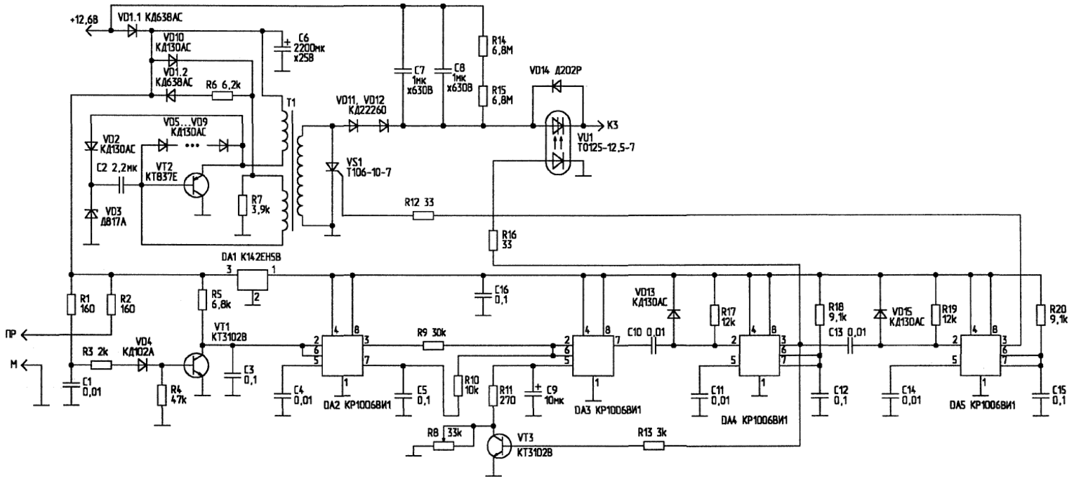
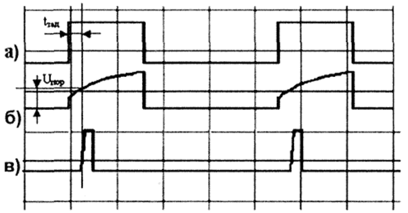
Just in case, we recall that at different speeds, 1 ms corresponds to very different angles of rotation of the engine crankshaft. To create an octane corrector, another timer (DA427) of the KR3VI1006 type and a VT1 transistor are additionally introduced into the OH-3 circuit, which are connected immediately after the breaker contact bounce protection circuit on the VT1 and DA2 elements. Figure 4 shows the timing diagrams of the octane corrector. The signal from the output of the anti-bounce circuit, i.e. from pin 3 DA2 (Fig. 4a), enters the proportional-integrating chain R9-R10-C5.
Conclusion 7 DA2 is connected to the integrator capacitor C5, which forms the pulse shape necessary for the operation of the device (Fig. 4b). The leading edge of this pulse corresponds to the set ignition timing of the mixture in the engine cylinder. If there was no connection between C5 and pin 7 of DA2, C5 would be discharged through the same resistors (R9, R10) through which it was charged, which would not allow the device to work stably at high engine speeds. From the integrating chain, the signal is fed to the input of the threshold element, the role of which is played by the DA4 timer. The timer provides the ability to adjust the response threshold of internal comparators, which, with a certain shape of the input signal, allows you to smoothly adjust the delay of the output pulse relative to the positive front of the input. Figure 4 considers the case when the comparator response threshold Uthr is brought to a relatively flat section of the integrated pulse, which makes it possible, by changing the response threshold, to select the required delay value. The pulse that controls the power switch on the VU1 optothyristor is generated by the DA4 timer (Fig. 4c). The same pulse is applied to the base of the transistor VT3, included in the circuit of the internal divider of the reference voltage of the timer DA3. The divider is a chain of three 5 kΩ resistors connected in series. To facilitate understanding of the principle of operation of the timer, it is shown in Fig. 5 in a slightly "opened" form.
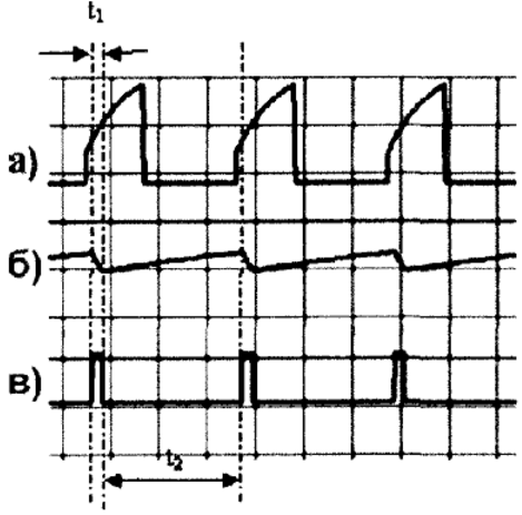
The regulating resistor R8 is connected through the limiting resistor R11 to the pin 5 of the timer, that is, in parallel with its two "lower" resistors of the internal reference voltage divider. For normal operation of the engine, the additional delay introduced with the help of an octane corrector should decrease with an increase in engine speed, that is, the device must also include a frequency meter. This problem turned out to be easy to solve. Timer DA4, which controls the power switch, generates control pulses with a duration of 1 ms. The same pulses are used for the frequency counter. It turned out that the frequency dependence of the input delay time is easiest to organize on the same DA3 chip that regulates the ignition timing. For this, capacitor C5 is connected to terminal 3 of the DA9 timer. It is desirable to use this capacitor type K53-16 or some similar one with a capacitance tolerance of no more than ± 10%. Capacitor C9 is charged through the internal divider of the timer, and is discharged through the open transistor VT3 and the R8-R11 circuit in its collector circuit. Figure 6 shows the phase relationship of the signals at some points of the octane-corrector circuit. Figure 6a shows the pulses at the DA3 input, and Figure 6b shows the voltage waveform at its internal reference voltage divider.
Capacitor C9, connected to pin 5 of DA3, is discharged through the key to VT3 during time t1, and charged through the internal divider of the timer during time t2. But since t1 is constant (at a given position of the engine R8), and t2 changes with the change in the engine speed, the reference voltage will also change when the shaft speed changes. The required charge and discharge rates of the capacitance can be selected by setting the appropriate values of C9 and R11. Certain restrictions on the choice of capacitance are imposed by the internal divider of the timer, since the resistors that make it up are fixed and have a resistance of 5 kOhm. The third diagram (Fig. 6c) shows the signal generated by the DA4 timer that controls the power switch VU1. It is strictly normalized in duration, since it is also used in a frequency meter, controlling a key on a VT3 transistor. The critical part of the circuit is the transformer shown in Figure 7. Its workmanship must be high, as it works in a hard mode. It is best to fill it with varnish or epoxy. The number of turns, the winding order and the placement of the windings are shown in Table 1.
The winding order of the windings is 1-3-2. Winding - ordinary, layered, coil to coil. Insulation between the windings and layers - 1 layer of varnished fabric (breakdown voltage - about 1000 V). Transformer core - ferrite 2000NM1 Sh10x10. It is assembled with a gap of 1 mm (a dielectric spacer is used). The developed block allows the engine to operate on a very lean air-fuel mixture. With this mode of operation, not only a very noticeable fuel economy is observed (it can reach 20%), but also a decrease in the CO content in the exhaust gases. The latter is below the sensitivity limit of gas analyzers used in the traffic police. So it is quite realistic, having installed such a block on the Zaporozhets, to ride it to Paris. The Euro emission standard will be met without any platinum catalysts. In addition, when using this unit on vehicles running on natural gas, the engine starts freely without gasoline even at low temperatures. Sources of
Author: V. Shcherbatyuk, E. Petsko
Artificial leather for touch emulation
15.04.2024 Petgugu Global cat litter
15.04.2024 The attractiveness of caring men
14.04.2024
▪ A hungry microbe will not touch ▪ PNX1700 Single Chip Media Processor ▪ Full HD Projector LG TV Mini Beam Master
▪ section of the site Cultivated and wild plants. Article selection ▪ article What a word is a sentence! Popular expression ▪ article Who was the first to brew coffee? Detailed answer ▪ article Not with a pump, but with a can. Tourist tips ▪ article Nine-band KB antenna. Encyclopedia of radio electronics and electrical engineering ▪ article Domino chain with a gap. Focus Secret
Home page | Library | Articles | Website map | Site Reviews www.diagram.com.ua |


 Arabic
 Bengali
 Chinese
 English
 French
 German
 Hebrew
 Hindi
Hindi Italian
 Japanese
 Korean
 Malay
Malay Polish
 Portuguese
 Spanish
 Turkish
 Ukrainian
 Vietnamese


 (1)
(1)


 Leave your comment on this article: