|
|


 Arabic
 Bengali
 Chinese
 English
 French
 German
 Hebrew
 Hindi
Hindi Italian
 Japanese
 Korean
 Malay
Malay Polish
 Portuguese
 Spanish
 Turkish
 Ukrainian
 Vietnamese
|
ENCYCLOPEDIA OF RADIO ELECTRONICS AND ELECTRICAL ENGINEERING VHF converter with notch filter. Encyclopedia of radio electronics and electrical engineering
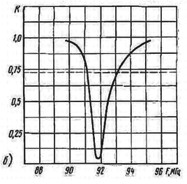
Encyclopedia of radio electronics and electrical engineering / Civil radio communications Reception of remote VHF FM radio stations can be difficult or impossible due to interference from a local TV or VHF FM transmitter. The author of the published article solved the problem of such interference by introducing a notch filter converter at the VHF FM input. The simplest passive single-link serial or parallel filters at a load of 75 ohms have a low quality factor and. hence, a too wide rejection band. Combined filters from serial and parallel oscillatory circuits have the best parameters (Mishustin I.A. Improving the noise immunity of amateur radio reception. - M .: Energy, 1974). As practice has shown, the notch filter L1C1C2 has good quality (Fig. 1a). Its frequency response, taken with the X1-7B device, is shown in Fig. 1b. The rejection bandwidth at the level of K = 0,707 is no more than 2 MHz with a suppression depth of at least 25 dB.
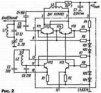
Taking into account all of the above, a VHF converter was developed for receiving radio stations in the VHF-1 band to a receiver with a VHF-2 band (Fig. 2). The input and output of the converter are combined, so a separate antenna is not required.
Specifications:
The local oscillator of the converter is made on transistors VT2, VT5 of the DA1 microcircuit with a minimum number of frequency-setting elements - L2, C3 and C6. In this design, the mixer outputs 2 and 3 of the microcircuit are loaded onto a symmetrical coil L3. This provides a balance of pairs of transistors VT1, VT3 and VT4, VT6 of the differential stage for both direct and alternating currents and, as a result, an increase in sensitivity. It is also important to ensure the optimal value of the collector currents of the mixer transistors, which affects the noise level. For the K174PS1 microcircuit, the minimum noise level is achieved at a total current of differential pairs of transistors of about 1 mA. The input signal through the capacitor C5 is fed to the base of the transistors VT1, VT6. In the differential stage, it is mixed with the local oscillator signal, converted in frequency and fed to the output through capacitor C4. In the output spectrum there is a total component, which contains the signals of VHF-1 radio stations, transferred to the frequency range of the VHF-2 band. The converter uses resistors MLT - 0,125, capacitors KM or KT, C2 - tuning type KT4-21. For tuning stability, it is desirable that capacitors C1 - C3 and C6 have a minimum TKE value. The local oscillator coil L2 is wound turn to turn on a frame with a diameter of 8 mm with a trimmer from an armored magnetic circuit SB-1 a and contains 5 turns of PEV or PEL wire with a diameter of 0,56 mm. With the same wire turn to turn, but without a frame, a coil L5 is wound on a mandrel with a diameter of 3 mm, which contains 10 turns with a tap from the middle. Coil L1 is made of wire with a diameter of 0.95 mm and contains 4 turns wound on a mandrel with a diameter of 5 mm with a small pitch. All parts are placed on a single-sided printed circuit board made of foil fiberglass with a thickness of 1 ... 2 mm (Fig. 3). The elements of the local oscillator and the input circuits are separated by a printed conductor, which acts as a "screen." A coil frame L8 is glued into a hole with a diameter of 2 mm. A hole with a diameter of 3 mm is intended for attaching the converter to the radio receiver chassis. The converter is powered by a radio receiver with a stabilized voltage of 6 ... 12 V and consumes current within 1.5 ... 4 mA.
To adjust the notch filter, a high-frequency millivoltmeter is connected to the output of the receiver's IF path. The AGC system (if any) should be disabled. Having tuned the radio receiver to an interfering signal, by rotating the rotor of capacitor C2 they achieve a minimum of a millivoltmeter. With fine tuning of the filter, the signal at the output of the IF path I should fall by 25 ... 30 times. If such suppression is not achieved, then the capacitance of the capacitor C1 should be more accurately selected. In the absence of a device, the filter is tuned "by ear" for maximum suppression of side reception channels. Most of the side channels should disappear, and useful signals from VHF-1 radio stations should appear in their place. The L2 local oscillator coils are tuned to the required range. guided by the frequencies of known radio stations. At the end of this setting, fill all the coils and the L2 coil trimmer with paraffin (or other moisture-resistant compound). The minimum noise level is achieved by selecting the resistor R3. It is preferable to do this during a transmission pause when the noise is not masked by speech or music. For accurate selection, the resistor R3 can be made up of two, for example, parallel-connected resistors with a resistance of 10 and 15 ohms. Author: A.Pakhomov, Zernograd, Rostov region
Air trap for insects
01.05.2024 The threat of space debris to the Earth's magnetic field
01.05.2024 Solidification of bulk substances
30.04.2024
▪ Scientists know how to increase computer performance by 20% ▪ Vizio P Series Ultra HD Smart TVs ▪ Smart driver's seat responds to driver gestures ▪ There is water on the asteroid Cybele
▪ section of the site Winged words, phraseological units. Selection of articles ▪ article Adhesive plaster. History of invention and production ▪ article Why bulls pounce on red clothes? Detailed answer ▪ article The functional composition of Panasonic TVs. Directory ▪ article Shoe lace knot. Focus Secret
Home page | Library | Articles | Website map | Site Reviews
www.diagram.com.ua |


 Leave your comment on this article: