|
|


 Arabic
 Bengali
 Chinese
 English
 French
 German
 Hebrew
 Hindi
Hindi Italian
 Japanese
 Korean
 Malay
Malay Polish
 Portuguese
 Spanish
 Turkish
 Ukrainian
 Vietnamese
|
ENCYCLOPEDIA OF RADIO ELECTRONICS AND ELECTRICAL ENGINEERING Transmitting attachment to the R-250M2. Encyclopedia of radio electronics and electrical engineering
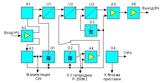
Encyclopedia of radio electronics and electrical engineering / Civil radio communications The prefix is designed to work with the R-250M2 radio receiver, which has a second local oscillator output, but it can also be used with receivers of other modifications (R-250, R-250M). In this case, matching stages must be built into their second local oscillators. The set-top box can also work as an independent transmitter at discrete frequencies. The transceiver is built according to a triple frequency conversion scheme (see Fig. 1) and provides operation in CW, SSB and AM modes in all amateur KB bands. The power supplied to the final stage is 40 watts.
In SSB mode, a single-sideband signal generated at node A1 at a frequency of 500 kHz, mixed in a mixer UI with a voltage of 7285 kHz from a crystal oscillator G1, is converted into a voltage of the first intermediate frequency equal to 7785 kHz. In the second mixer U2, the signals of the first intermediate frequency and the second local oscillator of the receiver (comes through the RF amplifier A4) or an additional quartz oscillator G2 are summed. The value of the second intermediate frequency depends on the frequency of the second local oscillator of the receiver (additional quartz oscillator) and can vary within 9500 ... 11500 kHz (see Table 1). Table 1. Block output frequencies on different ranges, kHz
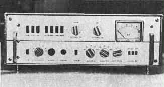
Note. The output frequency of block A1 is 500 kHz, G1 is 7285 kHz, U1 is 7795 kHz. The signal to the operating frequency, which lies within the amateur KB bands, is formed in the mixer U3, where the voltages of the second IF and the crystal oscillator G3 are mixed. The frequency of the latter depends on the range used (see Table 1). From the output of the mixer U3, the signal enters the pre-terminal two-stage amplifier A5, and then to the output stage A6. In CW and AM modes, the SSB signal conditioner A3 is disabled, the generator G1 generates a voltage with a frequency of 7785 kHz, and the mixer U1 acts as an RF amplifier. The passage of signals in these modes is similar to that described above. The schematic diagram of the attachment is shown in fig. 2. It is built on a block principle. Some of the nodes are similar to those used in the transceiver set-top box designed by Ya. Lapovka (see "Radio", 1978, No. 8, pp. 12-16) and will not be considered in detail here. The blocks are interconnected by a bundle. The pin numbers of the blocks and wires are the same, so one of them is indicated on the diagram. 1 unit. Here the SSB signal is formed and transferred to a frequency of 7785 kHz. On the high-frequency ranges, the upper side band is transmitted, on 40 and 80 meters - the lower one. The transition from one band to another occurs automatically. On the ranges of 10, 15, 20 m, a crystal oscillator on a 1V1 transistor generates a signal with a frequency of 500 kHz. On the remaining ranges, the 1K1 relay connects quartz with a resonant frequency of 503,7 kHz to it. The signal of the first IF at the output of the block is selected by a band-pass filter consisting of coils 1LI-1L3 and capacitors 1C18, 1C19, 1C21, 1C23. block 2 acts as a microphone amplifier. The signal from its output (pin 22) through the contacts of switch S1 in SSB mode is fed to a balanced mixer in block 1, and in AM mode to the gate of transistor 9V1. With the help of relay 2K1, the voltage level at the output of the microphone amplifier changes in the clipping mode of the SSB signal. From the collector of the 2V1 transistor, the signal is fed to the VOX system. block 3 is designed to automatically control the set-top box when switching from reception to transmission. The block consists of an amplifier on a 3A1 chip and an actuator on transistors 3V5-3V7. The block is controlled by signals coming from a microphone amplifier (in SSB and AM modes) or from keying circuits (in CW mode). To prevent the operation of the VOX system during reception from the output of the low-frequency receiver R-250M2 through a rectifier on diodes 3V1, 3V2, a voltage is applied to pin 2 of the ZA1 microcircuit, closing its output transistors. The time during which the set-top box is held in a given state (during transmission) depends on the capacitance of the 3C8 capacitor. With the capacity indicated on the circuit diagram, it is about 1,1 s. The output circuit of the actuator includes a control coil 3L1 reed switch 3S1, which, during transmission, connects the corresponding points of the quartz oscillators and the RF amplifier to the common wire. During reception, a -9V voltage is supplied to the listed nodes and the output stage (through the 4V6 transistor) through the control circuits through the resistor R1 and diode V12, which prohibits their operation. block 4 is an oscillator whose signal frequency is determined by a quartz resonator. In CW and AM modes, the 4K1 relay, controlled by switch S1, connects 4V1 quartz to the 4V1 transistor at a frequency of 7785 kHz, in SSB mode - 4V2 at a frequency of 7285 kHz. In CW mode, manipulation is carried out in the collector circuit of the 4V1 transistor. The output of the generator (pin 12) is connected to one of the gates of the transistor 1V9. block 5 - the second mixer, assembled on a double-gate field-effect transistor 5V1. The signal of the second intermediate frequency is selected by a tunable bandpass filter, consisting of coils 5L1-5L3, variable capacitors 5C7, 5C9. 5С11 and constant 5С4-5С6, 5С8. 5S10. block 6 contains an RF amplifier on a 6A1 chip and an additional crystal oscillator on a 6V1 transistor. The frequency of the generated signal is determined by quartz 6V1-6V6 or connected to the X5 connector ("External quartz"). Power is supplied to the generator only when the button S4 ("Sq. Gen.") is pressed. In this case, the 6K1 relay is activated, and instead of the amplified signal of the second local oscillator of the receiver, a signal is supplied to the output of the block (pin 61) from an additional quartz oscillator - the set-top box starts to work as. independent transmitter. The generator in block 6 is not a mandatory set-top box. However, in some cases, it increases its operational capabilities. For example, making a general call on a quartz frequency can detun the receiver. Instead of a generator with a fixed frequency, you can use a smooth local oscillator, but this will somewhat complicate the design of the attachment (it will be necessary to make a vernier-scale device). block 7 - the third mixer. The signal with a frequency lying in the amateur KB ranges is separated by a band-pass filter included in the drain circuit of the 7V1 transistor. block 8 contains a range quartz oscillator on an 8V2 transistor and an emitter follower on an 8V1 transistor. The signal from the output of this block (pin 81) is fed to the third mixer. block 9 consists of broadband (on a 9V1 transistor) and resonant (on 9V2) RF amplifiers and an electronic key on a 9V4 transistor. The transmission coefficient of the broadband amplifier and, therefore, the output power of the set-top box can be adjusted by changing the mixing voltage at the second gate of the 9V1 transistor, supplied from the divider across resistors R1 -R5. In AM mode, a low-frequency signal from a microphone amplifier is fed to the same shutter. The resonant RF amplifier has no features. One of the broadband circuits is included in the collector circuit of the 9V2 transistor. (selected by switch S3.6) tuned to the middle of the corresponding amateur KB band. An electronic key, the input of which is connected to the VOX system, controls the operation of the power amplifier. block 10 - power amplifier assembled on a 10V1 lamp. The matching of the amplifier with the antenna provides a P-loop. The receiver antenna is connected to it through a capacitor 10C5. Diodes 10V2, 10V3 protect the receiver from overload when the radio is transmitting. block 11 - power unit. It has no features .. Relay K1, controlled by the S12 button, supplies high voltage to the power amplifier. The operation of the set-top box is controlled by the RA1 device, which is connected by switch S2 to the grid, anode and output circuits of the power amplifier. The appearance of the console is shown in Fig. 3. Structurally, the high-frequency blocks, except for block 10, are mounted on one printed circuit board made of foil fiberglass 3 mm thick. The arrangement of parts on it is shown in Fig. 4 (conditionally the board is divided into two parts). The biscuits of range switches and quartz resonators are fixed on the board using racks or corners. On fig. 5 shows the placement of the printed circuit board (highlighted in color), the output stage, the power supply inside the set-top box.
Partitions-screens between the blocks are made of strips of double-sided foil fiberglass with a thickness of 1.5 and a height of 40...45 mm. The resulting grid is installed after mounting all the elements on the board and soldered to the board using copper pins. It should only be taken into account that the grating should not have contact with the "earth" areas of the blocks. It is attached to the body at only one point. The partitions must be provided with holes for the axis of the range switch, electromechanical filter. Filter screens can be made in a similar way. The block of variable capacitors is located next to the filter of the second mixer and is well shielded. On fig. 4, the connection of the "earth" platforms of the blocks to each other is not shown. In principle, they can be connected by jumpers arbitrarily, but during excitation it may be useful to select the grounding point in each of the units of the set-top box. The wiring diagram of the low-frequency units is not shown. A board with dimensions of 200x40 mm with these blocks is shielded and placed on the left end side of the attachment. The winding data of the inductors are shown in Table. 2. Coils in bandpass filters are preferably made on ring cores made of ferrite 30 HF or 50 HF. In this case, the filter gain will increase. Table 2. Winding data of inductors.
The power transformer is made on the ShL20X40 magnetic core. Winding I contains 884 turns of wire PEV-2 0,47. Taps are made from the 478th turn (127 V), 806th (+10 V), 845th (Norm) and 884th (-10 V). Winding II contains 1050+1050 turns of PEV-2 0,27 wire, winding III - 165+165 turns of PEV-2 0,33, winding IV - 27+27 turns of PEV-2 0.96. winding V - 45 turns of wire PEV-2 0,47. Switches S1 - S13 - P2K, the rest - biscuit. Relay K1 with a response voltage of 12 V. The relay contacts are designed for switching circuits with a voltage of 1000 V. The remaining relays are RES-15. passport RS4.591.003. The PA1 instrument is a microammeter with a total deflection current of 100 μA. Preliminary adjustment of the set-top box is carried out according to the usual method - the correct installation, the operation of the power supply, quartz oscillators, and a microphone amplifier are checked. According to a well-known technique, the operation of the SSB signal generator and all mixers is checked. When adjusting the filters in the first and second mixers, the gates of the field-effect transistors are disconnected from the previous stages, and a signal from the generator is applied to one of the gates. Mixing cascades should be adjusted. achieving the maximum undistorted signal at their outputs (controlled by an oscilloscope). Due to the significant scatter in the parameters of field-effect transistors, the values of the levels in the mixers are not given. Some approximate levels and recommendations for setting up such nodes are indicated in the article by Ya. Lapovka "Transceiver set-top box" (see "Radio", 1978, No. 8, pp. 12-16). Working with an attachment. The high-frequency input of the X6 set-top box must be connected to the output of the second local oscillator of the R-250M2 receiver. The set-top box is tuned to a frequency when the high voltage is turned off. By pressing the "Settings" button and setting the appropriate range, the filter of the second mixer is adjusted to the maximum grid current of the output lamp. The output stage is powered by a combined rectifier. When the high voltage is turned off, a reduced voltage is supplied to the anode and screen grid of the output lamp, which is determined by the zener diode circuit in the screen circuit. This makes it possible not only to set up the P-loop with the high voltage turned off, but also to conduct local communications. For long-distance communications, high voltage must be turned on. In conclusion, it should be said that radio amateurs with category II or III can enter the 160-meter amateur band into the prefix (instead of the 15 m band). To do this, instead of quartz at a frequency of 10 MHz, use quartz at 8 MHz. The corresponding circuits in the third mixer, RF amplifier and output stage should be rewound and tuned to a frequency of 1850...1950 kHz. When operating on this range, the output power of the set-top box should be reduced to 5 watts.
Author: E. Sukhoverkhov (UA3AJT, ex UI8HC), Moscow; Publication: N. Bolshakov, rf.atnn.ru
Machine for thinning flowers in gardens
02.05.2024 Advanced Infrared Microscope
02.05.2024 Air trap for insects
01.05.2024
▪ New professional A3 scanners ▪ Digital voice recorder with laser beam ▪ Samsung 8 GB LPDDR4 mobile memory modules
▪ section of the site Biographies of great scientists. Article selection ▪ article The guard is tired. Popular expression ▪ article Which currency began to be denoted by the sign $ before the dollar? Detailed answer ▪ Article Actinidia Amur. Legends, cultivation, methods of application ▪ article Transmitting prefix to R-250M. Encyclopedia of radio electronics and electrical engineering
Home page | Library | Articles | Website map | Site Reviews
www.diagram.com.ua |

 Leave your comment on this article: