
|
|
ENCYCLOPEDIA OF RADIO ELECTRONICS AND ELECTRICAL ENGINEERING
Section 4. Switchgears and substations Switchgears and substations with voltages above 1 kV. Open switchgears
Encyclopedia of radio electronics and electrical engineering / Rules for the installation of electrical installations (PUE) 4.2.45. In outdoor switchgear of 110 kV and above, passage should be provided for mobile assembly and repair mechanisms and devices, as well as mobile laboratories. 4.2.46. The connection of flexible wires in the spans should be carried out by crimping using connecting clamps, and the connections in loops at the supports, the connection of branches in the span and the connection to the hardware clamps - by crimping or welding. In this case, the connection of branches in the span is performed, as a rule, without cutting the wires of the span. Soldering and twisting wires are not allowed. Bolted connections are allowed only on the terminals of devices and on branches to arresters, surge arresters, coupling capacitors and voltage transformers, as well as for temporary installations for which the use of permanent connections requires a large amount of work on rewiring tires. Insulator garlands for busbar suspension in outdoor switchgear can be single-circuit. If a single-chain garland does not meet the conditions of mechanical loads, then a double-chain garland should be used. Separating (mortise) garlands are not allowed, with the exception of garlands, with the help of which high-frequency barriers are suspended. The fastening of flexible busbars and cables in tension and suspension clamps in terms of strength must comply with the requirements given in 2.5.84. 4.2.47. Connections of rigid busbars in spans should be made by welding, and busbar connections of adjacent spans should be made using compensating devices attached to the busbars, as a rule, by welding. It is allowed to attach compensating devices to spans using bolted connections. Branches from rigid tires can be made both flexible and rigid, and their connection to spans should be carried out, as a rule, by welding. Connection by means of bolted connections is permitted only upon justification. 4.2.48. Branches from the busbars of the outdoor switchgear, as a rule, should be located below the busbars. Busbar suspension with one span over two or more sections or busbar systems is not allowed. 4.2.49. Wind and ice loads on tires and structures, as well as design air temperatures, must be determined in accordance with the requirements of building codes and regulations. In this case, the deflection of rigid tires should not exceed 1/80 of the span length. When determining the loads on structures, the weight of a person with tools and mounting devices should additionally be taken into account when applying:
The tension of the descents to the switchgear devices should not cause unacceptable mechanical stresses and unacceptable convergence of wires under the design climatic conditions. 4.2.50. The calculated mechanical forces transmitted during a short circuit by rigid tires to the support insulators should be taken in accordance with the requirements of Ch. 1.4. 4.2.51. The safety factor of mechanical strength under loads corresponding to 4.2.49 should be taken:
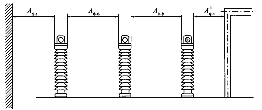
4.2.52. Supports for fastening outdoor switchgear tires should be calculated as intermediate or end in accordance with Ch. 2.5. 4.2.53. Layouts of outdoor switchgear 35 kV and above are recommended to be carried out without the upper tier of tires passing over the switches. 4.2.54. The smallest clear distances between non-insulated current-carrying parts of different phases, from non-insulated current-carrying parts to the ground, grounded structures and fences, as well as between non-insulated current-carrying parts of different circuits should be taken from Table. 4.2.5 (Fig. 4.2.3 - 4.2.12). In the event that in installations located in high mountains, the distances between the phases increase in comparison with those given in Table. 4.2.5 according to the results of the corona test, the distances to grounded parts must be increased accordingly. Table 4.2.5. The smallest clear distances from current-carrying parts to various elements of outdoor switchgear (substations) 10-750 kV, protected by arresters, and outdoor switchgear 220-750 kV, protected by surge arresters1), 2), 3), 4), 5), (in the denominator) (Fig. 4.2.3 - 4.2.12)
1. For insulation elements under a distributed potential, the insulation distances should be taken into account the actual values of the potentials at different points on the surface. In the absence of data on the potential distribution, a straight-line law of the potential drop along the insulation from the full rated voltage (on the side of current-carrying parts) to zero (on the side of grounded parts) should be conventionally assumed. 2. The distance from current-carrying parts or insulation elements (on the side of live parts) under voltage to the dimensions of transformers transported by rail, it is allowed to take less than the size 'B', but not less than the size A1f-z. 3. The distances Af-z, A1f-z and Af-f for outdoor switchgear 220 kV and above, located at an altitude of more than 1000 m above sea level, must be increased in accordance with the requirements of state standards, and the distances Af-f, 'B' and 'D1' must be checked against corona restriction conditions. 4. For a voltage of 750 kV, the table gives the distances Af-f between parallel wires with a length of more than 20 m; distances Af-f, between screens, crossing wires, parallel wires up to 20 m long for 750 kV outdoor switchgear with arresters are 7000 mm, and for 750 kV outdoor switchgear with surge arresters - 5500 mm. 5. Surge arresters have a protective level for limiting switching surges phase - ground 1,8 Uph.
4.2.55. The smallest clear distances with rigid tires (see Fig. 4.2.3.) between the current-carrying and grounded parts Af-z and between the current-carrying parts of different phases Af-f should be taken according to Table. 4.2.5, and for flexible (see Fig. 4.2.4) - should be determined as follows: Af-z.g = Af-z + α ; A1f-z = A1f-z.g + α ; Af-f.g = Af-f + α ; where α=f sin(a); f - sag of wires at a temperature of +15 ºС, m; a=arctg(P/Q); Q - calculated load from the weight of the wire per 1 m of the length of the wire, daN/m; P - calculated linear wind load on the wire, daN/m; in this case, the wind speed is assumed to be 60% of the value selected in the calculation of building structures. 4.2.56. The smallest allowable clear distances between energized adjacent phases at the time of their closest approach under the action of short-circuit currents must be at least those given in Table. 2.5.17, taken according to the highest operating voltage. In a flexible busbar made of several wires in a phase, in-phase spacers should be installed. 4.2.57. The smallest distances from live parts and insulators under voltage to permanent internal fences should be (Table 4.2.5, Fig. 4.2.5):
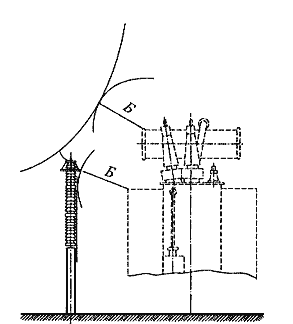
4.2.58. Current-carrying parts (terminals, buses, slopes, etc.) may not have internal fences if they are located above the planning level or ground communication structures at a height of at least the values \u4.2.5b\u4.2.6bcorresponding to the size 'G' according to Table. XNUMX (Fig. XNUMX.). Unshielded current-carrying parts connecting the capacitor of high-frequency communication, telemechanics and protection devices with the filter must be located at a height of at least 2,5 m. In this case, it is recommended to install the filter at a height that allows repair (adjustment) of the filter without removing voltage from the connection equipment. Transformers and devices, in which the lower edge of porcelain (polymeric material) of insulators is located above the level of planning or ground communication facilities at a height of at least 2,5 m, it is allowed not to fence (see Fig. 4.2.6). At a lower height, the equipment must have permanent fences that meet the requirements of 4.2.29, located from transformers and apparatus at distances not less than those given in 4.2.57. Instead of permanent fences, it is allowed to install canopies that prevent the maintenance personnel from touching the insulation and live equipment. 4.2.59. Distances from unshielded current-carrying parts to the dimensions of machines, mechanisms and transported equipment must be at least size 'B' according to Table. 4.2.5 (Fig. 4.2.7.).
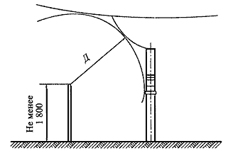
4.2.60. The distances between the nearest unshielded current-carrying parts of different circuits must be selected from the condition of safe maintenance of one circuit with the second one not disconnected. When unshielded current-carrying parts of different circuits are located in different (parallel or perpendicular) planes, the vertical distances must be at least the size 'B', and horizontally - the size 'D1' according to Table. 4.2.5 (Fig. 4.2.8). In the presence of different voltages, the dimensions 'B' and 'D1' are taken at a higher voltage. The size 'B' is determined from the condition of servicing the lower circuit with the upper one not disconnected, and the size 'D1' is the service of one circuit with the other not disconnected. If such maintenance is not provided, the distance between current-carrying parts of different circuits in different planes should be taken in accordance with 4.2.53; in this case, the possibility of wires approaching under operating conditions (under the influence of wind, ice, temperature) should be taken into account.
4.2.61. The distances between the current-carrying parts and the upper edge of the outer fence must be at least the size 'D' according to the table. 4.2.5 (Fig. 4.2.10).
4.2.62. The distances from the moving contacts of the disconnectors in the off position to the grounded parts must be at least Af-z and A1f-z; before the busbar of its phase connected to the second contact - not less than the size 'Ж'; before busbars of other connections - not less than the size Af-f according to the table. 4.2.5 (Fig. 4.2.11).
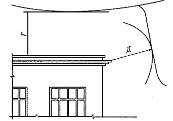
4.2.63. The distances between the current-carrying parts of the outdoor switchgear and buildings or structures (ZRU, control room, transformer tower, etc.) horizontally must be at least 'D' size, and vertically with the greatest sagging of wires - not less than 'G' size according to Table. 4.2.5 (Fig. 4.2.12).
4.2.64. Laying of overhead lighting lines, overhead communication lines and signaling circuits above and below the live parts of the outdoor switchgear is not allowed. 4.2.65. Distances from hydrogen warehouses to outdoor switchgear, transformers, synchronous compensators must be at least 50 m; to the VL supports - at least 1,5 support heights; to the buildings of the substation with the number of cylinders stored in the warehouse up to 500 pcs. - not less than 20 m, over 500 pcs. - not less than 25 m; to the outer fence of the substation - at least 5,5 m. 4.2.66. Distances from openly installed electrical devices to SS water coolers must be at least the values given in Table. 4.2.6. For areas with calculated outdoor temperatures below minus 36 ºС, given in Table. 4.2.6 distances should be increased by 25%, and with temperatures above minus 20 ºС - reduced by 25%. For reconstructed objects given in Table. 4.2.6 distances may be reduced, but not more than 25%. Table 4.2.6. The smallest distance from openly installed electrical devices to SS water coolers
4.2.67. Distances from switchgear and substation equipment to ZRU buildings and other technological buildings and structures, to design bureaus, STK, SK are determined only by technological requirements and should not increase due to fire conditions. 4.2.68. Fire-prevention distances from oil-filled equipment with an oil mass of 60 kg or more in a piece of equipment to industrial buildings with room categories B1-B2, D and D, as well as to residential and public buildings must be at least:
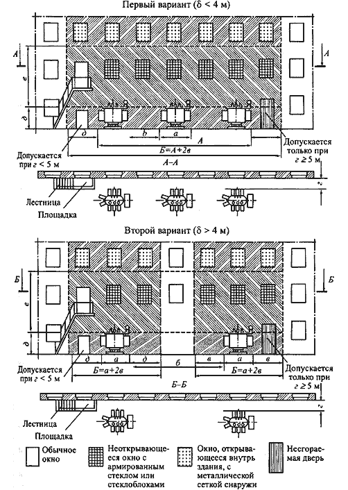
When installing oil-filled transformers with an oil mass of 60 kg or more, electrically connected to the equipment installed in these buildings, near the walls of industrial buildings with room category G and D, distances less than those indicated are allowed. At the same time, at a distance of more than 10 m from them and outside the sections with a width of 'B' (Fig. 4.2.13), there are no special requirements for the walls, windows and doors of buildings. At a distance of less than 10 m to transformers within sections of width 'B', the following requirements must be met: 1) up to the height 'D' (up to the level of input of transformers) windows are not allowed; 2) with a distance 'r' of less than 5 m and fire resistance grades of buildings IV and V, the wall of the building must be made according to fire resistance grade I and rise above the roof made of combustible material by at least 0,7 m; 3) at a distance 'r' of less than 5 m and degrees of fire resistance of buildings I, II, III, as well as at a distance 'r' of 5 m or more without restriction on fire resistance at a height of 'd' to 'd' + 'e', non-opening windows filled with reinforced glass or glass blocks with frames made of fireproof material; above 'd' + 'e' - windows that open into the building, with openings equipped with metal mesh from the outside with cells no larger than 25x25 mm; 4) at a distance of 'r' less than 5 m at a height of less than 'd', and at a 'r' of 5 m or more at any height, doors made of non-combustible or slow-burning materials with a fire resistance limit of at least 60 minutes are allowed; 5) ventilation inlets in the wall of the building at a distance 'r' less than 5 m are not allowed; exhaust openings with the emission of uncontaminated air within the specified limit are allowed at a height of 'd'; 6) at a distance of 'd' from 5 to 10 m, ventilation holes in the enclosing structures of cable rooms on the side of transformers in a section with a width of 'B' are not allowed. Shown in fig. 4.2.13 dimensions 'a'-'g' and 'A' are taken up to the most protruding parts of the transformers at a height of not more than 1,9 m from the ground. With a unit power of transformers up to 1,6 MVA, distances 'v' ≥1,5 m; 'e' ≥8 m; more than 1,6 MVA 'v' ≥2 m; 'e' ≥10 m. Distance 'b' is taken according to 4.2.217, distance 'd' must be at least 0,8 m. The requirements of this paragraph also apply to outdoor PTS.
4.2.69. To prevent oil spreading and fire spread in case of damage to oil-filled power transformers (reactors) with an oil quantity of more than 1 ton per unit, oil receivers, oil drains and oil collectors must be made in compliance with the following requirements: 1) the dimensions of the oil receiver must protrude beyond the dimensions of the transformer (reactor) by at least 0,6 m with an oil mass of up to 2 tons; 1 m with a mass of 2 to 10 tons; 1,5 m with a mass of 10 to 50 tons; 2 m with a mass of more than 50 tons. In this case, the size of the oil receiver can be taken less than 0,5 m from the side of a wall or partition located at a distance of less than 2 m from the transformer (reactor); 2) the volume of the oil receiver with oil removal should be designed for a one-time reception of 100% of the oil poured into the transformer (reactor). The volume of the oil receiver without oil drainage should be designed to receive 100% of the volume of oil poured into the transformer (reactor) and 80% of water from fire extinguishing agents based on the irrigation of the oil receiver areas and side surfaces of the transformer (reactor) with an intensity of 0,2 l / s m2 within 30 minutes; 3) the arrangement of oil receivers and oil drains should exclude the flow of oil (water) from one oil receiver to another, the spread of oil over cable and other underground structures, the spread of fire, clogging of the oil drain and clogging it with snow, ice, etc.; 4) oil receivers for transformers (reactors) with an oil volume of up to 20 tons can be made without oil drainage. Oil receivers without oil drainage should be made of a recessed structure and closed with a metal grate, on top of which a layer of clean gravel or washed crushed granite with a thickness of at least 0,25 m, or non-porous crushed stone of another rock with particles from 30 to 70 mm should be poured. The level of the full volume of oil in the oil receiver must be at least 50 mm below the grate. The removal of oil and water from the oil receiver without draining the oil must be provided by mobile means. In this case, it is recommended to perform a simple device to check the absence of oil (water) in the oil receiver; 5) oil receivers with oil drainage can be made both buried and not buried (the bottom is at the level of the surrounding layout). When making a recessed television receiver, the installation of side rails is not required if this ensures the volume of the oil receiver specified in clause 2. Oil receivers with oil diversion can be performed: with the installation of a metal grate on the oil receiver, on top of which gravel or crushed stone is poured with a layer thickness of 0,25 m; without a metal grate with gravel filling on the bottom of the oil receiver with a layer thickness of at least 0,25 m. An unburied oil receiver should be made in the form of side guards for oil-filled equipment. The height of the side railings should be no more than 0,5 m above the level of the surrounding layout. The bottom of the oil receiver (submerged and non-buried) must have a slope of at least 0,005 towards the pit and be covered with cleanly washed granite (or other non-porous rock) gravel or crushed stone with a fraction of 30 to 70 mm. The thickness of the backfill must be at least 0,25 m. The upper level of gravel (crushed stone) must be at least 75 mm below the upper edge of the side (when oil receivers are installed with side rails) or the level of the surrounding layout (when oil receivers are installed without side rails). It is allowed not to backfill the bottom of the oil receivers over the entire area with gravel. At the same time, the installation of flame arresters should be provided for on systems for removing oil from transformers (reactors); 6) when installing oil-filled electrical equipment on a reinforced concrete floor of a building (structure), an oil drain is mandatory; 7) oil drains must ensure the removal of oil and water from the oil receiver used to extinguish a fire, by automatic stationary devices and hydrants to a fire-safe distance from equipment and structures: 50% of the oil and the full amount of water must be removed in no more than 0,25 hours Oil drains can be made in the form of underground pipelines or open cuvettes and trays; 8) oil collectors should be of a closed type and should contain the full volume of oil of individual equipment (transformers, reactors) containing the largest amount of oil, as well as 80% of the total (taking into account a 30-minute supply) water consumption from fire extinguishing equipment. Oil sumps must be equipped with a water presence alarm with a signal output to the control panel. The internal surfaces of the oil receiver, the guards of the oil receiver and the oil sump must be protected by an oil-resistant coating. 4.2.70. At substations with 110-150 kV transformers with a unit capacity of 63 MVA or more and transformers of 220 kV and above with a unit capacity of 40 MVA or more, as well as at substations with synchronous compensators for fire extinguishing, a fire-fighting water supply system powered by an existing external network or from an independent source of water supply. It is allowed to provide for water intake from ponds, reservoirs, rivers and other reservoirs located at a distance of up to 200 m from the substation using mobile fire fighting equipment instead of a fire-fighting water pipeline. At substations with 35-150 kV transformers with a unit capacity of less than 63 MVA and 220 kV transformers with a unit capacity of less than 40 MVA, fire water and a reservoir are not provided. 4.2.71. KRUN and PTS of outdoor installation should be located on a planned site at a height of at least 0,2 m from the planning level with a service platform near the cabinets. In areas with a height of calculated snow cover of 1,0 m and above and a duration of its occurrence for at least 1 month, it is recommended to install outdoor KRUN and KTP at a height of at least 1 m. The location of the device should provide convenient rolling out and transportation of transformers and the withdrawable part of the cells.
The world's tallest astronomical observatory opened
04.05.2024 Controlling objects using air currents
04.05.2024 Purebred dogs get sick no more often than purebred dogs
03.05.2024
▪ SHARP DV-HRW30 - VHS VCR, DVD and HDD recorder
▪ section of the site Car. Article selection ▪ article Tobacco smoking: impact on the human body, consequences. Basics of safe life ▪ article How old is wrestling? Detailed answer ▪ Ruskus article. Legends, cultivation, methods of application ▪ article Parametric sensors. Encyclopedia of radio electronics and electrical engineering
Home page | Library | Articles | Website map | Site Reviews www.diagram.com.ua | ||||||||||||||||||||||||||||||||||||||||||||||||||||||||||||||||||||||||||||||||||||||||||||||||||||||||||||||||||||||||||||||||||||||||||


 Arabic
 Bengali
 Chinese
 English
 French
 German
 Hebrew
 Hindi
Hindi Italian
 Japanese
 Korean
 Malay
Malay Polish
 Portuguese
 Spanish
 Turkish
 Ukrainian
 Vietnamese






 See other articles Section