
|
|
ENCYCLOPEDIA OF RADIO ELECTRONICS AND ELECTRICAL ENGINEERING Solid-state relays of the KR293 series. Encyclopedia of radio electronics and electrical engineering
Encyclopedia of radio electronics and electrical engineering / Reference materials Integrated hybrid microcircuits of the KR293 series are DC and AC signal switches with optoelectronic isolation between input and output. In terms of their electrical parameters and functionality, these microcircuits can replace electromechanical relays in many areas of technology. This circumstance determined the wide use of the term "solid-state relay" in the literature to denote integrated circuits of a new series of switching devices, the principle of operation of which was considered in sufficient detail in the Radio magazine N2 for 1995. COMPOSITION OF THE SERIES Currently, the KR293 series includes five types of solid state relays KR293KP1 KR293KP5, each of which is formed by devices of two ratings, for example, KR293KP1 and KR293KP11. In turn, each chip type contains three groups (group A, B and C). Conditional graphic images of integrated circuits of a series of solid state relays are shown in Fig.1. Single-channel relays KR293KP1AV, KR293KP11AV, KR293KP3AV and KR293KP31AV are made in a rectangular plastic six-pin package 2101-6, and two-channel microcircuits KR293KP2AV, KR293KP21AV, KR293KP4AV, KR293KP41AV, KR293KP5AV and KR293 51KP2101AV - in an eight-pin package type 8-XNUMX. Microcircuits KR293KP1 KR293KP5 are designed for switching signals of both direct and alternating current, and KR293KP11 KR293KP51 - only direct. Solid-state relays KR293KP1AV, KR293KP11AV, KR293KP2AV and KR293KP21AV have so-called normally open contacts, i.e. correspond to type A relays, and KR293KP3AV, KR293KP31AV, KR293KP4AV and KR293KP41AV are type B relays with normally closed contacts. Microcircuits KR293KP5AV and KR293KP51AV can perform the functions of a type C relay, working for switching.
Fig. 1 The classification of microcircuits into groups within each rating is carried out according to the values of the maximum permissible switching voltage Ucom and the value of the output resistance of the solid-state relay in the open state Rout physically associated with it (Table 1). Table 1
Obviously, it is not advisable to use the ratings KR293KP2AV, KR293KP4AV and KR293KP5AV instead of KR293KP21AV, KR293KP41AV and KR293KP51AV for DC switching due to the high output resistance, and the ratings KR293KP1AV and KR293KP3AV have a certain advantage over cheaper KR293KP11AV and KR293KP31AV, as they allow, if necessary, It is possible to reduce the output impedance of the device by two, working in a special switching mode, when the 4th and 6th pins of the microcircuit are combined and connected to the positive, and pin 5 to the negative potential of the circuit, respectively. The parameter values given in Table1 correspond to the following measurement modes (Table 2): Table 2
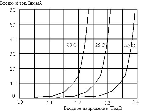
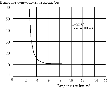
ELECTRICAL CHARACTERISTICS OF THE RELAY Solid-state relays of all ratings of the KR293 series are unified in terms of input characteristics, which are determined by the parameters of the infrared light-emitting diode used in the device. The dependence of the forward input voltage Vin and the output resistance Rout on the level of the input current in the temperature range is shown in fig. 2 and 3, respectively.
It should be noted that a decrease in the input current relative to the nominal value, in addition to a direct increase in the output resistance, also leads to a wide spread in the values of this parameter, while an increase in input currents practically does not improve the static characteristics of the device. When using a relay for switching an analog signal in linear circuits, it should be taken into account that the output current-voltage characteristic of the device is non-linear outside the output voltage range of -0.7 ... 0.7 V, as shown in Fig.4. due to the shunting action of the built-in drain-to-source diode of the MOSFETs.
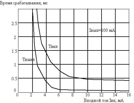
The value of the input current has a noticeable effect on the dynamic parameters of the solid state relay. From the above figure 5 it can be seen that you should not work at an input current below the rated current. At the same time, it must be taken into account that the KR293 series microcircuits retain high reliability indicators if the average input current does not exceed 20 mA.
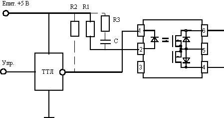
A simple circuit that allows you to get the required input current and voltage for reliable control of a solid state relay is shown in Fig.6.
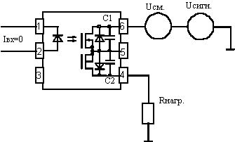
Fig. 6 Resistor R1 sets the input current level, and resistor R2 is used if the control circuit has a high level leakage current so large that it does not allow maintaining the voltage at the input of the microcircuit less than 0.8 V. In the case when it is required to reduce the turn-on time of the device, it is recommended supplement the RC circuit with a chain of impulse control of the LED. At the moment of switching, a pulse current flows through the LED, determined by an RC circuit consisting of resistor R3 and capacitor C. The magnitude of the pulse current should not exceed the maximum allowable value for the relay of 150 mA, it should also be remembered that the maximum allowable reverse voltage level on the LED is not must exceed 3V. THERMAL CHARACTERISTICS OF THE RELAY A solid state relay is a semiconductor device that retains its functionality and high level of reliability if the operating temperature of the pn junction, Tp, does not exceed 125°C. Heat can be supplied to the microcircuit both from the environment, the temperature of which is Tc, and as a result of heat release in the device itself as a result of resistive heating, mainly in the output circuits of the device when current flows. The degree of overheating of the pn junction is determined by the value of the so-called thermal resistance of the crystal - the environment, Rk-s, which for all ratings of the KR293 series microcircuits is 60 ° C / W. The permissible power Po(T), which can be dissipated by the device at a given temperature, is determined by the following relationship: Po(Tc) = ( Tp - Tc ) / Rp-s (1) Thus, using the dependence of the output resistance of the device in the open state on temperature, it is possible to determine the permissible average operating load current at a given ambient temperature. Because, P(Tc) = (Iout)2 * Rout(Tp) (2), then from (1) and (2) we get: Iout = ( Tp - Ts ) / Rp-s Rout(Tp) 1/2 (3) For example, let's determine the value of the permissible load current of the KR293KP1B microcircuit at Tc = 85°C. The output resistance of the device at a temperature of 25°C is 25 Ohm (see Table 2), and the ratio Rout (125C) / Rout (25C) according to the graph in the figure is 1.6, then Rout (125C) = 25 * 1.6 = 40 Ohm. Now, using (3), we find Iout = ( 125 - 85 ) / (60 * 40) 1/2= 0.12 (A) Note that expression (1) should also be used to determine the limiting output current in the off state, which, at given values of the ambient temperature Tc and the maximum allowable voltage at the output in the off state Ukom, should not exceed the values calculated according to the following formula: Iout P(Ts)/Ucom = ( Tp - Ts ) / ( Rp-s * Ucom) (4) So for the KR293KP1B microcircuit at Tc equal to 85C, we find Iout (125 - 85) / (60 * 250) = 280 (μA). Although it is not a valid operating mode for the device to be in a breakdown state, an assessment of adverse conditions must be made in advance, which is especially important when operating on an inductive load. OUTPUT CAPACITY OFF This capacitance is essentially the capacitance of the reverse-biased drain-to-substrate diode of the MOSFET in the state where no drive current flows through the LED. It is obvious that this capacitance provides an undesired passage of the AC signal to the load when the relay is turned off. A simplified relay equivalent circuit for AC is shown in Figure 7.
Fig. 7 To reduce the output capacitance of the device, the property of reducing the barrier capacitance of the diode with increasing reverse bias at the pn junction is used. Bias must be applied to one of the output contacts of the relay, while the bias voltage and the maximum amplitude of the alternating signal in total must not exceed the maximum allowable voltage at the output of the device in the off state. Such a method of supplying a bias is shown in Fig. 8.
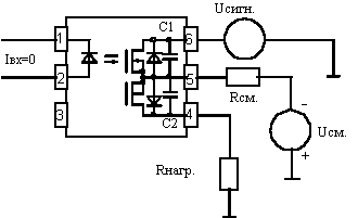
Fig. 8 With this method, one of the diodes of the MOSFETs will be under reverse bias, the other diode in this case will have zero bias. There is another way to apply bias voltage. It consists in using a negative voltage source, which, for example, is available in telephone exchanges. The minus of the source through a high-resistance resistor is connected to the 5th output of the microcircuit, as shown in Fig. 9, while both diodes will be under reverse bias. The total output capacitance in this case will be two times less than with the first method of applying a bias.
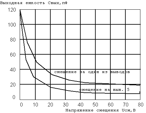
Bias resistor Rcm. prevents shunting of the load and signal source in the state when the relay is on and must be much larger than the load resistance. When closed, the bias resistor must be much smaller than the capacitance to prevent modulation of the bias voltage by capacitive currents. For example, for switching circuits of telephone exchanges with Rload.=600 Ohm, Fsign.=1000 kHz and Cout.=20pF, the value of Rcm should lie in the range of 0.5 ... 5 MΩ. Figure 10 shows a graph of the output capacitance of the relay versus the bias voltage.
INSULATION VOLTAGE The relay parameter "isolation voltage" characterizes the ability of the relay to withstand a test voltage of 1500 V applied between input and output for one minute. The controlled parameter is the leakage current, which should not exceed 10 μA. During the production process, 100% control of devices is carried out for the stability of the relay when an insulation voltage of 1800 V is applied for 5 seconds. The isolation voltage value of 1500 V is sufficient for most industrial applications of the relay, where the supply voltage does not exceed 220 V. For applications associated with increased requirements for the reliability and electrical safety of equipment (medical equipment, energy), a group with an isolation voltage of 4000 V is produced. It should be specially noted that the insulation voltage is a test voltage applied to the device for a short time and the manufacturer does not guarantee that the device will be under this voltage for a long time. Author: Zeshkov Yu., Pervouralsk, Sverdlovsk region ; Publication: N. Bolshakov, rf.atnn.ru
A New Way to Control and Manipulate Optical Signals
05.05.2024 Primium Seneca keyboard
05.05.2024 The world's tallest astronomical observatory opened
04.05.2024
▪ Collective electron tunneling ▪ A new neural interface has been developed ▪ Quantum effects for fast battery charging
▪ section of the site Art video. Article selection ▪ article Motoblock with a trolley. Drawing, description ▪ article In which country can you see commercials that have become a TV series? Detailed answer ▪ article Repair and testing of oxygen station cylinders. Standard instruction on labor protection ▪ article Indicators on neon lamps. Encyclopedia of radio electronics and electrical engineering ▪ article Handkerchief and disappearing money. Focus Secret
Home page | Library | Articles | Website map | Site Reviews www.diagram.com.ua | |||||||||||||||||||||||||||||||||||||||||||||||||||||||||||||||||||||||||||||||||


 Arabic
 Bengali
 Chinese
 English
 French
 German
 Hebrew
 Hindi
Hindi Italian
 Japanese
 Korean
 Malay
Malay Polish
 Portuguese
 Spanish
 Turkish
 Ukrainian
 Vietnamese




 Leave your comment on this article: