|
|


 Arabic
 Bengali
 Chinese
 English
 French
 German
 Hebrew
 Hindi
Hindi Italian
 Japanese
 Korean
 Malay
Malay Polish
 Portuguese
 Spanish
 Turkish
 Ukrainian
 Vietnamese
|
TOOLS AND MECHANISMS FOR AGRICULTURE
Motoblock with a trolley. Drawing, description
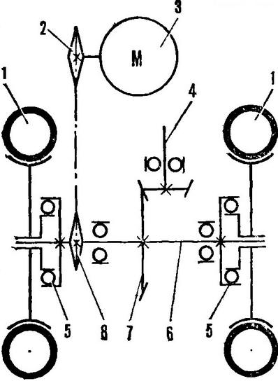
Directory / Tools and mechanisms for agriculture The walk-behind tractor was built by members of the "Young Technician" circle of SPTU No. 25 from the city of Kelmentsy, Chernivtsi region. With its help, potato plots are processed, grass is mowed, and goods are transported. The layout of the walk-behind tractor is traditional: a frame, an engine and a two-wheeled chassis. As needed, they are joined to it: in front of a mower driven by a power take-off shaft; behind - a single-hull plow with a support wheel; three lancet paws of a cultivator or a harrow (through a hitch); cargo trolley (through the hinge assembly). As in many similar machines, components and assemblies from the Vyatka and Electron scooters were used in the design of the walk-behind tractor and the trolley. These are the VP-150M engine, wheels, frame, steering wheel, electrical equipment, seat. The wheels were taken from a decommissioned Cultivator, the bevel gear drive of the conveyor shaft, cutterbar and reel - from the ZhVN-6 header, overrunning clutches - from the SZUG-3, 6 grain seeder, the fuel tank - from the trigger motor of the YuMZ-6 tractor. The transmission of the walk-behind tractor is mechanical, gear-chain. It consists of two sprockets with 10 and 44 teeth, a chain with a pitch of 19,05 mm and a pair of bevel gears with a gear ratio of 1,4 to the power take-off shaft brought forward. Technical data of the walk-behind tractor
The differential in the transmission was abandoned, as this would require the introduction of a wheel locking mechanism, which, firstly, complicates the design, and secondly, makes it difficult to maneuver in small plots. Therefore, two overrunning clutches were used, which allow slipping of the drive wheels. The power unit of the walk-behind tractor is a frame (Fig. 3). It is based on a cross member - a corner of 75x40 mm, in which four holes are drilled: two Ø 14,2 and two Ø 12,2 mm. Two M12 bolts are welded into the latter from the inside of the frame. They are used for attaching the attachment of agricultural implements and the hinged assembly of the cargo trolley.
On the left, a carrier beam is welded to the cross member - a corner 67x67 mm with a cutout measuring 166x39 mm in a vertical shelf under the gearbox housing. At the front, the beam ends with a support for the parking bipod bracket. On the right, a carrier plate measuring 200x38x8 mm is welded to the cross member, designed, like the beam, for fastening the gearbox. The under-engine frame (Fig. 5) is a plate measuring 280x40x8 mm, to the middle of which an engine mounting clamp from a 76X5 mm pipe is welded. Elongated holes were also made here for tensioning the drive chain by moving the entire under-engine frame relative to the frame of the walk-behind tractor.
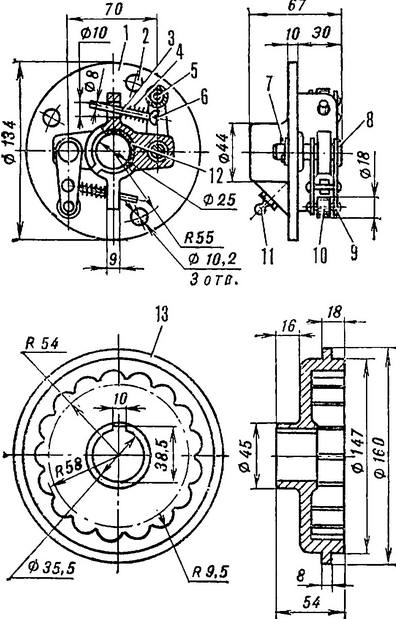
A vertical rod - a bar Ø 20 mm - is welded to the plate in front, and a front engine mounting bracket is welded to it - a corner 20x20 mm with a longitudinal hole in the horizontal shelf, which serves to adjust the position of the engine on the frame and eliminate chain skew. A 20x6 mm cutout was made in the vertical shelf of the corner for installing the clutch cable sheath stop. Torque from the output shaft is transmitted to the chain by the drive sprocket; It is made of a hub - an old sprocket from the Vyatka scooter, the teeth of which are ground down to Ø 34 mm - and a ten-tooth sprocket with a central hole Ø 30 mm. They are welded together, as shown in Figure 4. When assembled, the walk-behind tractor is small. In order to further reduce its dimensions, the standard muffler of the scooter engine was replaced with a self-made, more compact one (Fig. 13) and in no way inferior to the factory one in terms of work quality. For its manufacture, a part of the Vyatka muffler was used - a pipe with a belt. It is inserted into a cup Ø 75 and 65 mm high and connected to the ring by welding. A hole is drilled in the glass for the exit of exhaust gases. The muffler is mounted directly on the exhaust port of the engine cylinder. The engine is started, as on a scooter, with a kickstarter. Fuel flows to the carburetor by gravity. Gear shifting is carried out by a lever welded to the gearbox sector. However, the main controls of the walk-behind tractor - gas and clutch levers - are displayed on the control knobs of the attachment and steering wheel of the cargo trolley. The walk-behind tractor bridge is shown in Figure 6. To install overrunning clutches, the gearbox shaft had to be lengthened by 170 mm (on the left by 100 mm and on the right by 70 mm). To do this, central holes Ø 8 and a depth of 30 mm were drilled in its ends and an M10 thread was cut. Rods 130 and 100 mm long were screwed in there, welded to the shaft, machined to Ø 25 mm, and M20 threads 40 mm long were cut at the ends. Drilled holes Ø 3,2 mm for cotter pins. On the left end of the shaft, a driven sprocket with 44 teeth and the leading part of the left overrunning clutch were installed on a common key (for this, its seat was machined to Ø 35,5 mm and the keyway was milled). The same groove was made on the right side of the shaft. The driven parts of the couplings were not altered, only three holes were drilled in them for attaching the wheel disks from the cultivator. Of course, if desired, it would be possible to make a new running shaft, it is shown in Figure 7. Overrunning clutch (Fig. 8) works as follows. When the shaft rotates, the leading part with its cells rests against the driven roller and makes it rotate. When turning the walk-behind tractor, the wheel moving in a circle of a larger radius rotates faster than the shaft, and the leading part of the clutch, respectively, faster than the driven one. Therefore, the rollers, compressing the springs, slip over the cellular surface (soft clicks are heard). When the speed of rotation of the wheel decreases, the rollers re-engage with the cells. A nylon bushing is pressed into the inner cavity of the driven part of each overrunning clutch. The "running shaft-sleeve" interface is lubricated with grease through an oiler. For the attachment (Fig. 9), cultivator units were used. Twin rods are shortened and welded to the docking channel. It also has longitudinal holes for attaching to a walk-behind tractor.
The tie-rods end with a bracket-holder of agricultural implements with a hole for their racks and a locking screw. Pipes of control handles are welded to the channel from above. Their ends are flattened, and holes are drilled in them for installing a steering wheel with gas and clutch levers. The hinge assembly (Fig. 12) is made from the steering shaft of the scooter. The shaft is shortened to 460 mm, and a yoke of the automobile driveline joint is welded to it from below. The mating fork was removed, and plates 135 mm long were put on and welded to the ends of the cross. The lower ends of the plates are beveled and welded to the channel. In the latter, longitudinal holes were also made for attaching the trolley to the frame of the walk-behind tractor. The hinge assembly is lubricated through an oiler. At the heart of the trolley frame (Fig. 11) is the frame of the Vyatka or Electron scooter. From below, two corners 35x35 mm 870 mm long are welded to it. Their rear free ends are connected by a third corner 500 mm long. There are also two forks from the front suspension of the Vyatka (the stop of the wheel brake drum housing is welded into the right one), interconnected by a horizontal half-inch pipe. A U-shaped subframe made of 35x35 mm corners is also welded to it and to the main frame of the scooter. To install the body, two hinge bushings are attached to the horizontal pipe. A simple body locking mechanism is installed on the transverse corner of the subframe: a locking lever, an eyelet, a spring and a guide sleeve. At a distance of 190 mm from the handle of the locking lever, a hole Ø 2,5 mm was drilled and a cotter pin was inserted into which the spring abuts. In the working position, the latch with its tip enters the front loop of the body mounting and holds it. The frame of the bogie body (Fig. 10) is made of corners 20x20 mm and sheathed with sheet steel 1,5 mm thick. A loop for fixing the body in the transport position is welded to it in front, and from the sides there are loops for connecting with hinge bushings, where fingers are inserted - steel rods Ø 17 mm. In conclusion, it remains to be said that it is easy to operate a walk-behind tractor. Members of our circle, for example, mastering in one lesson. The walk-behind tractor is also convenient for transporting goods. The driver sits on a shortened and turned 180 ° seat (with a tool box under it) and controls the walk-behind tractor, holding on to the standard handles left on the steering wheel. Author: V.Nikityuk
▪ Granular fertilizer dispenser ▪ Machine for manual transplantation
Machine for thinning flowers in gardens
02.05.2024 Advanced Infrared Microscope
02.05.2024 Air trap for insects
01.05.2024
▪ Secure quantum digital payments ▪ Technology developed to extract water from the moon ▪ A quantum processor woven from light ▪ Ionic thrust instead of reactive
▪ site section Welding equipment. Article selection ▪ article Abomination of desolation. Popular expression ▪ article Which goalkeeper could become a great hockey player, but chose football? Detailed answer ▪ article Diamond mountains. Nature miracle ▪ article Charger Tourist. Encyclopedia of radio electronics and electrical engineering
Home page | Library | Articles | Website map | Site Reviews
www.diagram.com.ua |


 See other articles Section