|
|
ENCYCLOPEDIA OF RADIO ELECTRONICS AND ELECTRICAL ENGINEERING Device for tuning KB antennas. Encyclopedia of radio electronics and electrical engineering
Encyclopedia of radio electronics and electrical engineering / Measuring technology When developing this measuring device, the goal was to produce a portable, simple design with sufficient accuracy for practical tuning of various KB antennas and having an autonomous power supply. The device allows you to make the following measurements: 1. Determine the resonant frequency of the antenna system, as well as the resonant frequencies of the elements included in it (vibrator, director, reflector) in the range of 31 ... 2.5 MHz.
The determination of all parameters, except for reactance, is carried out by direct reading from the scales of the device. The value of the reactive component is calculated according to well-known formulas. The device consists of two parts: a high-frequency bridge and a range generator, combined into one complete structure.
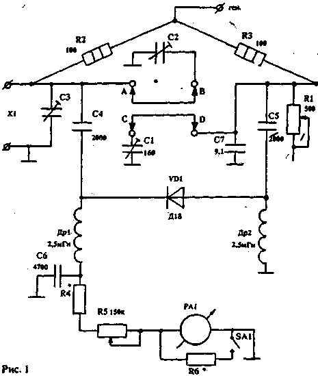
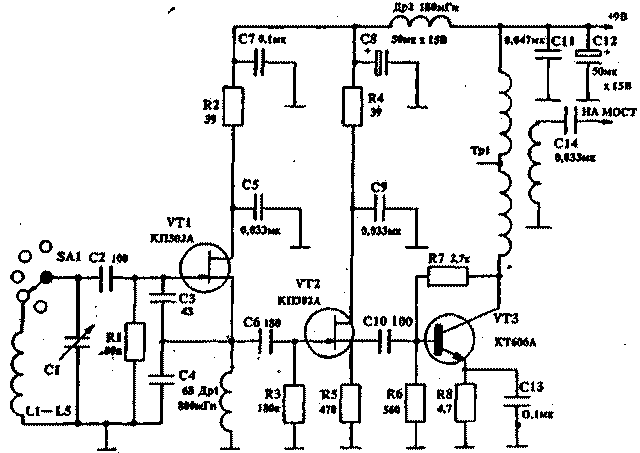
HIGH FREQUENCY BRIDGE The scheme shown in fig. 1, is a classic circuit of a measuring bridge on resistances (in one of the arms of this bridge there is a variable resistance R1 with a graduated scale). There is also a variable capacitor C1 with a capacity of 160 pF with a graduated scale, which, using two shorting jumpers, can be connected either in parallel to a variable resistance or to the bridge input, which allows it to be balanced in the presence of complex resistance. By the value of the capacitance of the variable capacitor, you can calculate the value of the reactive component of the load. The bridge is balanced using a 50 µA microammeter, which is connected to the diagonal. To adjust the sensitivity, a variable resistance R5 is used, in addition, using the SA1 toggle switch, a shunt resistance R1 is switched on in parallel with the RA6 microammeter, which coarsens the sensitivity of the indicator. The installation of the high-frequency part of the bridge is carried out with the shortest lengths of bare tinned wire with a diameter of 1,5 mm. RANGE GENERATOR The range generator (Fig. 2) covers the frequency range from 2,5 to 31 MHz. The range generator consists of a master oscillator assembled according to the capacitive three-point circuit on the KP302A transistor. With a switch, the circuits are included in the gate circuit. The entire range of the generator is divided into five sub-ranges in order to obtain a clear graduation of the scale. The next stage on the KP302A transistor is a source follower and serves to match the final stage of the generator assembled on the KT606A transistor. A broadband transformer on a ferrite ring is included in the collector circuit of this cascade, from the coupling winding of which high-frequency voltage is supplied directly to the bridge. The winding load is 100 ohms, although the bridge is balanced at lower voltages. CONSTRUCTION AND DETAILS. The device is assembled on a panel, which is placed in a box measuring 290x215x78 mm. When installing the device, it is necessary to exclude parasitic pickups on the bridge from the generator. Otherwise, it will not be possible to achieve full balance of the bridge during measurements. The location of parts and installation is shown in Fig.3. As a measuring resistance R1, it is necessary to use a variable non-inductive resistance that has a reliable contact of the slider with the conductive track. This device uses resistance with a graphite slider contact. The resistance R2 and R3 of the MLT type must be selected with an accuracy of 1%. Variable capacitor C1 - with an air dielectric with a maximum capacity of 160pf. Trimmers C2 and C3 - also with an air dielectric. Throttles Dr1 and Dr2 - three-section on a ceramic base. You can use any chokes with an inductance of 1 ... 2,5 mH. It is necessary that they have a minimum self-capacitance and do not have resonances in the frequency range of the generator. Microammeter RA1 - type M4205. The range generator uses a variable capacitor C1 with a capacity of 50 pF with an air dielectric, equipped with a vernier. The Tr1 transformer is wound with three wires of 9 turns in each section on a VCh50 ring with a diameter of 14 mm. ADJUSTMENT It is necessary to start setting up the device with a generator that has a minimum of harmonics, since their presence leads to measurement errors. It is necessary to carefully select, using capacitors C3 and C4, the connection of the circuit with the transistor VT1, as well as select the operating modes of this transistor and VT2 and VT3. After adjusting the range generator, they begin to adjust the high-frequency bridge. To do this, a constant resistance of 1..100 Ohm is connected to the input of the bridge X150, while the sockets A-B and C-D must be open. The generator frequency can be set to any, for example, 15 MHz. Then, the bridge is balanced with a variable resistance R1 at the maximum sensitivity of the indicator. In this case, the indicator readings may differ from zero. Then, by turning the C3 trimmer, the bridge is precisely balanced. With proper installation and the same value of resistance R2 and R3, the indicator needle should be at zero. Only very slight deviations are allowed. This operation neutralizes the capacitance of the variable resistance and the capacitance of mounting the opposite arms of the bridge. After that, jumpers A - B and C - D are inserted. and the capacitor C1 is set to the minimum capacitance position. Without touching the resistance R1, with the trimmer C2 we again achieve the balancing of the bridge - on the scale of the capacitor C1 we mark the zero point. This operation neutralizes the initial capacitance of the capacitor C1. From the zero point we calibrate the scale of the capacitor C1 every 10 pF. This completes the setup. USING THE APPLIANCE To measure the resonant frequencies of the antenna system and its elements, as well as the input impedance, the device is connected directly to the antenna input with a short piece of coaxial cable. If this is difficult - a half-wave (for a custom range) cable segment. This length of the connecting cable is necessary, since the half-wave line transmits the load parameters without transformation. To determine the resonant frequency of the antenna and its input impedance, we set the value of the variable resistance R1 equal to approximately the value of the wave resistance of the applied filler and, by changing the frequency of the range generator. find the frequency at which the indicator will show a sharp decrease in readings. Then, by changing the value of the resistance R1 and capacitance C1. as well as adjusting the frequency of the generator. we achieve a complete balance of the bridge. If the bridge is balanced at the zero position of the capacitor C1, then this means that the antenna at this frequency has a purely active input impedance, which is read from the resistance scale R I. If the balance required a change in the capacitor C1, then this means that the load has a reactive component the greater, the greater the capacity had to be entered during balancing. If the bridge is balanced when jumpers connect sockets A-B and C-D, then this means that the reactive component has a capacitive character. And if, when connecting nests A - C and B - D, then it is inductive in nature. The resonant frequencies of the directors and the reflector are measured in a similar way, but at the same time it is necessary to change the value of the resistance R1 over a wide range to find the resonant frequency. Balancing at this frequency may not be as sharp. as in determining the resonant frequency of an antenna. Also, you need to keep in mind. that when tuning antennas like HB9CV. having holes in the element, three frequencies will be clearly expressed: a short element - with a frequency above the working one, a long element - with a frequency below the working one, and a pronounced working frequency of the antenna. In addition to the operating frequency of the antenna and its main elements, resonant frequencies of booms, guy wires, etc. may appear. To determine the coefficient of shortening of coaxial cables and lines, the property of a half-wave line is used to transmit the load value without transformation. Therefore, we take a piece of cable or line and short-circuit one of the ends. We connect the other end to the input of the bridge, while setting the resistance R0 and the capacitor C1 to "1". Having found the resonant frequency at which the bridge will balance, we will keep in mind that for this frequency the given line has an electrical length of half a wave. Then, recalculating the frequency of the generator into a wavelength, we find the required half of the wave. By measuring the geometric length of a cable or line segment and calculating its ratio to a given half-wave, we obtain the shortening factor. With these measurements, it must be borne in mind that if a long cable is used, then several balance frequencies may be noted. The difference between two adjacent frequencies will give the frequency at which this line segment has a length of half a wave. It is easy to calculate the length of the desired phase-shifting line from the obtained shortening coefficient, since the half-wave segment of the line shifts the phase by more than 180°. For example, to shift the phase by 45°, you need to take a quarter of the half-wave line, and so on. Author: Y. Selevko (UA9AA); Publication: N. Bolshakov, rf.atnn.ru
The world's tallest astronomical observatory opened
04.05.2024 Controlling objects using air currents
04.05.2024 Purebred dogs get sick no more often than purebred dogs
03.05.2024
▪ Bottle of wine in a proton accelerator ▪ Started deliveries of samples of magnetoresistive memory ST-MRAM ▪ Program for the construction of synthetic DNA
▪ section of the site Radio - for beginners. Article selection ▪ article Repair of the door frame. Tips for the home master ▪ article Who is Lord Nelson? Detailed answer ▪ Guilin Mountain article. Nature miracle ▪ article Garland switch on a relay. Encyclopedia of radio electronics and electrical engineering ▪ article Colored water. Focus Secret
Home page | Library | Articles | Website map | Site Reviews www.diagram.com.ua |


 Arabic
 Bengali
 Chinese
 English
 French
 German
 Hebrew
 Hindi
Hindi Italian
 Japanese
 Korean
 Malay
Malay Polish
 Portuguese
 Spanish
 Turkish
 Ukrainian
 Vietnamese


 Leave your comment on this article: