|
|
ENCYCLOPEDIA OF RADIO ELECTRONICS AND ELECTRICAL ENGINEERING VHF FM receivers with PLL. Encyclopedia of radio electronics and electrical engineering
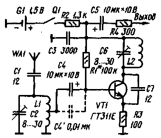
Encyclopedia of radio electronics and electrical engineering / radio reception Several simple VHF FM direct conversion receivers with phase locked loop (PLL) are offered to the attention of radio amateurs, implemented by direct synchronization of the local oscillator frequency with the received signal [1]. All designs use a radio receiver, the circuit of which is shown in Fig. 1. This is a frequency converter with a combined local oscillator, which simultaneously performs the functions of a synchronous detector. The input circuit L1C2 is tuned to the frequency of the received signal, and the local oscillator circuit L2C6 is tuned to a frequency equal to half of it. The conversion takes place at the second harmonic of the local oscillator, so the intermediate frequency lies in the audio range. The local oscillator frequency control functions are performed by the transistor VT1 itself, the output conductivity of which (it shunts the L2C6 circuit) depends on the collector current, and therefore on the output signal of the receiver.
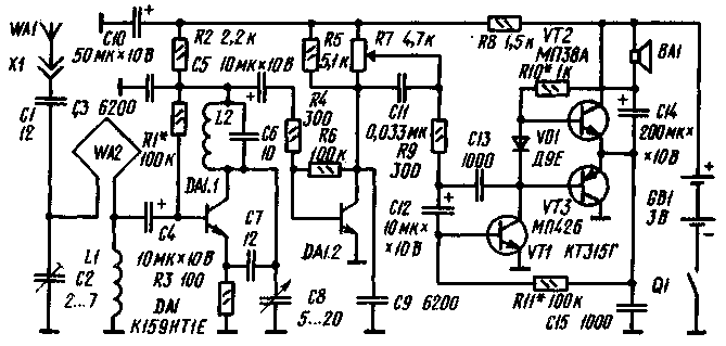
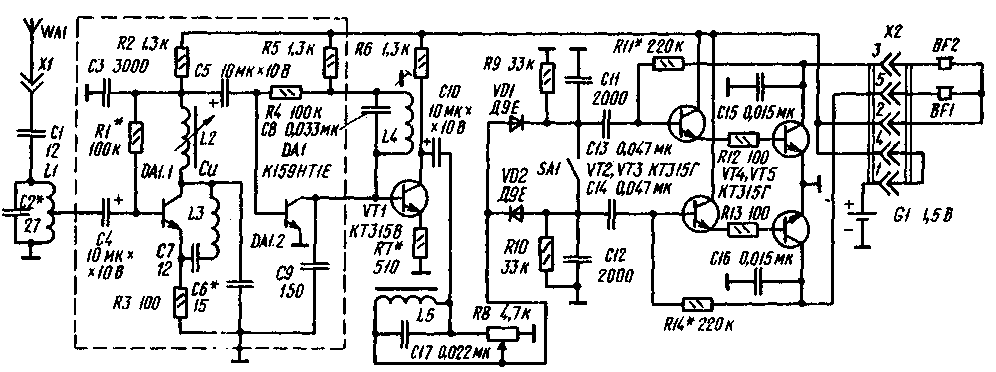
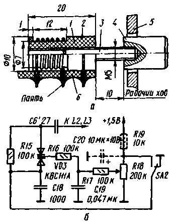
As a local oscillator, the transistor VT1 is connected according to the OB circuit, and as a frequency converter - according to the OE circuit. The input signal is fed to the base of the transistor from the L1C2 broadband circuit, tuned to the middle (70 MHz) frequency of the received range. The local oscillator is tuned in the frequency range of 32,9 ... 36,5 MHz, so that the frequency of its second harmonic lies within the boundaries of the VHF broadcasting range (65,8 ... 73 MHz). The efficiency of the receiver depends on the level of the second harmonic of the local oscillator oscillations in the collector current of the transistor VT1. In order to increase the amplitude of this component, the capacitance of the positive feedback capacitor C7 is chosen 2...3 times larger than it is required for generation at the fundamental frequency. As a synchronous detector, transistor VT1 is connected according to the OB circuit. It provides an amplification of the audio (intermediate) frequency signal, approximately equal to the ratio of the resistances of the resistors R2 / R3. The R2C3 circuit blocks the RF local oscillator and is the load of the synchronous detector. The time constant of this circuit allows you to skip the entire frequency band occupied by the complex stereo signal (CSS). When receiving only monophonic transmissions, the capacitance of the capacitor C3 can be increased to obtain a standard time constant of 50 µs. The voltage at the output of the receiver is 10...30 mV (this is enough to listen to radio broadcasts on phones switched on instead of resistor R2) and does not depend on the signal level of the received radio station. The described receiver is not inferior in sensitivity to the super-regenerative one, but unlike it, it does not "noise" in the absence of a signal. When the local oscillator is tuned to a frequency that is half the frequency of the radio station, a capture occurs, accompanied by a click, after which, in a certain retention band, the receiver "follows" the frequency of the received signal, performing its synchronous detection. The PLL and good decoupling of the input and heterodyne circuits (due to the large difference in their tuning frequencies) led to insignificant radiation into the antenna and made it possible to abandon the radio frequency amplifier. The disadvantage of the receiver is the excessive extension of the holdband with strong signals and their direct detection, however, this is more or less typical of all FM direct conversion PLL receivers. Silicon transistors can also be used in the receiver (for example, KT315V). Coils L1, L2 are frameless (inner diameter 5 mm, winding pitch 1 mm) and contain, respectively, 6 (with a tap from the middle) and 20 turns of wire PEV-2 0,56. A schematic diagram of a pocket radio that provides hands-free reception is shown in fig. 2. Reception is carried out on the WA2 loop antenna, tuned by the capacitor C2 to the middle of the VHF broadcasting range. Coil L1 serves to connect the antenna with the receiving device, which is assembled on one of the transistors of the DA1 microassembly and is tuned in range by the capacitor C8. The AF preamplifier is made on another microassembly transistor, the final one is on VT1-VT3 transistors. The output power of the amplifier at a load with a resistance of 8 ohms (dynamic head 0,25GD-10) when powered by two A332 elements (3 V) is 50 mW. When receiving weak signals, it is recommended to use an external antenna WA1 connected via connector X1. The receiver can be assembled in any suitable plastic case. A loop antenna (one turn of an insulated winding or mounting wire with a diameter of 0,3 ... 0,5 mm) is laid along its perimeter and fixed with glue. The approximate dimensions of the frame are 100x65 mm. The communication coil L1 is frameless (inner diameter - 5, winding pitch - 1 mm) and contains 2 ... 4 turns. Coil L2 can be the same as in the radio receiver according to the diagram in fig. 1. However, in order to avoid the microphone effect that may occur due to the acoustic connection between whose and the BA1 dynamic head, it is better to wind it round to round on a unified frame from a short-wave coil of a portable radio receiver (for example, the Okean brand) with a ferrite trimmer. In this case, it should contain 9 turns of wire PEV-2 0,27. A tuning capacitor with an air dielectric can serve as a tuning capacitor. Establishment begins with checking the modes of transistors. The voltage at the emitters of transistors VT2, VT3, equal to half the supply voltage, is set by selecting the resistor R11. Further, by short-circuiting the L2C6 local oscillator circuit and applying an AF signal of several millivolts to the emitter of the DA1.1 transistor. make sure it passes through the entire receiver path. The local oscillator mode is regulated by the selection of resistor R1, the level of the second harmonic - capacitor C7. The range limits are set by changing the inductance of the coil L2. The input circuit is tuned by capacitor C2, focusing on the maximum holding band of the signals of the received radio stations. On fig. 3 shows a schematic diagram of a simple stereo VHF FM receiver. To obtain maximum sensitivity, a serial oscillatory circuit L1.1C3, tuned to the middle of the VHF range, is included in the positive feedback circuit of the cascade on the transistor DA7. The receiver is tuned in range with the L2 variometer. The time constant of the R2C3 circuit allows you to skip the frequency band occupied by a complex stereo signal, with a roll-off at a frequency of 46,25 kHz of no more than 3 dB. A 1.2 kHz subcarrier frequency restore amplifier is assembled on the DA31,25 transistor. It is loaded with the L4C8 circuit tuned to this frequency, connected in series with the resistor R5. The resonant impedance of this circuit is chosen so that when it is fully turned on, a subcarrier frequency recovery level of 14 ... 17 dB is provided. (As follows from [2], the quality factor of the subcarrier frequency restorer circuit may differ from the standard one. This does not lead to nonlinear distortions during detection, while a decrease in crosstalk at frequencies below 300 Hz has practically no effect on the stereo effect). The buffer stage on the transistor VT1 is directly connected to the previous one. It has a low voltage gain (about two), high input impedance, and does not bypass the subcarrier recovery circuit. From the collector of the transistor VT1, polar-modulated oscillations through the volume control R8 arrive at the polar detector, made on diodes VD1, VD2. In order to simplify the design, the volume control is included in front of the detector. Elements L5 and C17 provide loudness, respectively, at lower and higher audio frequencies. The polar detector is loaded with R9C11 and R10C12 circuits. compensating pre-emphasis of the original stereo signals. When receiving monophonic transmissions, the polar detector is short-circuited by switch SA1. The AF stereo amplifier is assembled on transistors VT2-VT5, the output stage operates in mode A. The output power of the amplifier at a load with a resistance of 8 ohms is 1 ... 2 mW, the current consumption is 7 ... 8 mA. The amplifier can also work on stereo phones with a resistance of 8 ... 100 Ohms. The design of the variometer is shown in fig. 4a. Its body 1 is machined from fluoroplast, M5 thread is cut inside. The fastening clamp 2 is made of copper wire with a diameter of 0,5 mm, the trimmer pin 3 is made of brass. Tuning knob 4 - any ready-made or homemade. The number 5 indicates the receiver case, 6 - the circuit board.
The variometer coil L2 contains 16 turns of wire PEV-2 0.56, coils L1 and L3 (frameless, inner diameter 5, winding pitch 1 mm) - respectively 6 (with a tap from the middle) and 10 turns of the same wire. Coil L4 of the subcarrier frequency signal recovery circuit (155 turns) is wound with PEV-2 0,2 wire on a movable frame placed on a segment of a ferrite (M400NN) rod with a diameter of 8 and a length of 20 mm. The winding of the inductor L5 contains 500 turns of wire PEV-2 0,1, the magnetic circuit is made of permalloy plates Sh3Kh6. Capacitor C8 - KM-5 with a rated voltage of 50 V. When choosing a capacitor C3, it should be noted that it must have low inductance and low losses in the received frequency range. The power switch is combined with connector X2 (ONTS-VG-4-5/16-r socket, ONTS-VG-4-5/16-V plug), its function is performed by a jumper connecting pins 1 and 4. To eliminate the influence of hands on the local oscillator frequency of the cascades on the DA1 microassembly are placed in the screen. As an antenna, you can use a piece of steel wire 20 ... 30 cm long and 1 ... 1.5 mm in diameter. The free end of the wire should be bent, giving it the appearance of a ring. Electronic tuning can be entered into the receiver (Fig. 4, b). In this case, it is configured with a variable resistor R18. from the engine of which the bias voltage is supplied to the varicap VD3. The resistor is connected directly to the power supply of the receiver. At a voltage of 1,5 V, it is possible to cover approximately half of the range. The second half can be blocked by applying a forward bias to the varicap (in the left - according to the diagram - position of the SA2 switch). When using a device with a receiver according to the diagram in fig. 2, the supply voltage should be applied through the decoupling filter R19C20, and the SA2 switch should be excluded. Setting up the receiver begins with setting the operating mode of the output stages by selecting resistors R11, R14 (until the collector quiescent current of transistors VT5, VT6 is within 5 ... 8 mA). Next, check the frequency response of the stereo decoder. To do this, by short-circuiting the coil L2, a AF signal with a voltage of several millivolts is applied to the emitter of the transistor DA1.1. The output signal is removed from the resistor R8, having previously set its slider to the extreme left (according to the diagram) position, and the SA1 switch to the position shown in the diagram. The drop in frequency response at a frequency of 46,25 kHz should not exceed 3 dB (if necessary, this is achieved by selecting capacitor C3), and its rise at a frequency of 31,25 kHz (with the L4C8 circuit tuned) should be at least 14 dB (5 times). You can also configure the stereo decoder for the received stereo signal. To do this, a high-resistance millivoltmeter is connected in parallel with the contacts of the switch SA1 and by moving the coil L4 along the ferrite rod, the sub-carrier frequency recovery circuit is tuned to the maximum DC component at the output of the polar detector. With a tuned circuit, it should be 0.25 ... 0,3 V, and with an upset or short-circuited - 0,05 V. If necessary, select the resistor R7, achieving the maximum dynamic range of the cascade on the transistor VT2. On fig. Figure 5 shows a diagram of a VHF attachment to the industrial transistor receiver "VEF-202" [3] (positional designations of its parts according to the factory scheme are indicated in brackets). The prefix is mounted in the drum switch on the bar of the range 52.. 75 m. For tuning in the range, one of the sections of the capacitor of variable capacitance C3 is used, the reception is carried out on a telescopic antenna. The signal from the output of the set-top box is fed to the input of the AF amplifier through the housing of the drum switch. To do this, a flexible wire is soldered to the output of the set-top box, the second end of which (bent in the form of a ring) is connected to the switch housing using the mounting screw of the strap. The signal is taken from any fixed part of the switch (for example, from one of the mounting screws) and fed to the connection point of the resistor R29 and capacitor C71 of the receiver. Coils L1 (5 turns with a tap from the 2nd) and L2 (9 turns) are wound turn to turn with PEV-2 0,31 wire on frames from coils in the range of 52-75 m. Before installation, the switch bar is completely dismantled. Use a soldering iron to remove unnecessary contacts and install the missing ones. A tuning capacitor C2 is placed next to the antenna coil. The microassembly is installed in the hole for the third coil in the bar. When the set-top box is manufactured as a stand-alone unit, power should be supplied to any other receiver through the R7C10 decoupling filter. The supply voltage of the set-top box should be 3,5 ... 4,5 V. Literature 1. Polyakov V. Broadcasting FM receivers with phase-locked loop.- M.: Radio and communication, 1983.
Author: A.Zakharov, Krasnodar; Publication: N. Bolshakov, rf.atnn.ru
Artificial leather for touch emulation
15.04.2024 Petgugu Global cat litter
15.04.2024 The attractiveness of caring men
14.04.2024
▪ New application of ultrasonic devices ▪ Water purification and hydrogen production using artificial photocatalysis ▪ Efficient quantum dot solar panels ▪ Abandoned mines to save energy
▪ site section Indicators, sensors, detectors. Article selection ▪ article by Alfred Adler. Famous aphorisms ▪ article The skin of what animal did Hercules use as his only clothing? Detailed answer ▪ article Tricycle Triad-350. Personal transport ▪ article Low-budget metal detector. Encyclopedia of radio electronics and electrical engineering ▪ LPF article for the transceiver. Encyclopedia of radio electronics and electrical engineering
Home page | Library | Articles | Website map | Site Reviews www.diagram.com.ua |


 Arabic
 Bengali
 Chinese
 English
 French
 German
 Hebrew
 Hindi
Hindi Italian
 Japanese
 Korean
 Malay
Malay Polish
 Portuguese
 Spanish
 Turkish
 Ukrainian
 Vietnamese


 Leave your comment on this article: