|
|


 Arabic
 Bengali
 Chinese
 English
 French
 German
 Hebrew
 Hindi
Hindi Italian
 Japanese
 Korean
 Malay
Malay Polish
 Portuguese
 Spanish
 Turkish
 Ukrainian
 Vietnamese
|
ENCYCLOPEDIA OF RADIO ELECTRONICS AND ELECTRICAL ENGINEERING Low cost metal detector. Encyclopedia of radio electronics and electrical engineering
Encyclopedia of radio electronics and electrical engineering / metal detectors This unique metal detector is made from just five components - a cheap microcircuit, a variable capacitor, two search coils and an earpiece. But despite its simplicity, it has pretty good parameters. This circuit applies to metal detectors. And although it contains some components from other metal detectors, its principle of operation differs from them. It would not be an exaggeration to say that the characteristics of the circuit correspond to an inexpensive induction balance (IB) detector. Collect it - and you will see for yourself! This design is even simpler than the original beat detector, the schematic of which was published in EPE May 2004. In testing, the Old English Penny was found to be detectable in air at a distance of 15 cm, although due to various factors affecting sensitivity, the detection range can drop to 12,5 cm. Nevertheless, this detector can compete with budget IBs and even have some useful features inherited from beat detectors. Introduction Instead of using search and reference oscillators (as in beat detectors), or transmit and receive coils (as in IB detectors), this detector uses two transmitters (or search oscillators) with mutually overlapping coils as in IB detectors.
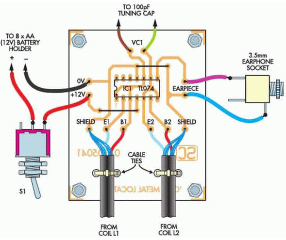
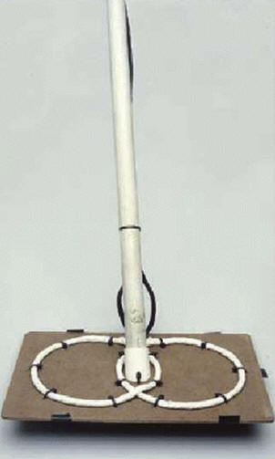
Note to the diagram: each coil contains 70 turns of PEL-0,32 wire wound on a mandrel with a diameter of 12 cm. The coils must overlap to produce tone in the headphones. As you can see from Figure 1, the circuit is very simple. Each oscillator is built around one quad op amp plus a search coil! The signals from these generators are mixed (similar to the type of beat detectors) and as a result, a beat signal can be heard. But besides all this similarity with beat detectors, there is also a difference. And this difference, which significantly increases the sensitivity of the detector, is that each of the coils changes the frequency of the generator through an inductive coupling. The result is a "balance" like that of IB detectors and the sensitivity becomes greater than that of beat circuits. In addition to all this, a means is required to control the output beat frequency so that the device can be tuned. This can be done in a number of ways, in this case using a standard 100 pF variable capacitor from an AM receiver connected between two oscillators. Since the concept of the circuit is borrowed from induction-balance and beat detectors, we will call the principle of operation of this detector "beat balance" (BB). Features The main characteristics of the scheme are:
scheme The design is based on the simplest generator on an inverter. Consider first the generator on IC1. From the moment the inductor begins to resist rapid voltage changes (called reaction), any change in the logic level at the output (pin 1) will be transmitted to the inverting input 2 with a time delay. The output voltage slew rate is approximately 8V/ms, all subsequent switching of IC1 is correspondingly delayed and thus the generator enters the operating mode, with steady oscillations at the output. One of the outputs of the search coil is connected to a non-inverting input (pin 3), which stabilizes the operation. In principle, pin 3 could be left unconnected, but that would be a suboptimal solution. Since different integrated circuits have different slew rates and input resistances, they are unlikely to work in this circuit. However, TL074CN is widely available and availability should not be a problem. The search coil is a critical part of the generator and it must be properly designed for the generator to work and the required output frequency to be obtained. This frequency should be large enough, but not so high that it is affected by noise or parameter instability. The characteristics of IC1 and the inductance of the coil affect the oscillating frequency, which is in the region of 260 kHz (without a Faraday shield connected). The Faraday screen increases the inductance of the coil by about a factor of two, respectively, the frequency at the output of the generator becomes about half as much. The oscillator on IC1b is turned on in exactly the same way as IC1a, except that its search coil is wired in anti-phase. As the search coil is moved parallel to the ground, the appearance of metal increases the inductance first L1 and then L2, or vice versa, causing the oscillation frequency to decrease slightly. A third amplifier, IC1c, is used to mix the signals of the two oscillators and produce a beat frequency in the audio range. All this is a distinctive feature of the BB type detector. The presence of metal not only changes the frequency of the search oscillator, but, just like with the IB detector, it affects the other coil. In fact, both poop influence each other through mutual induction, and this is the reason for a significant increase in the sensitivity of the system. In addition to all this, it is necessary to find a way to tune the detector. This is achieved by using a variable capacitor VC1, which is connected to two inductances (search coils). Almost any variable capacitor will work as VC1, it is desirable that it only have a not too large capacitance - from 47 pF to 100 pF. If this is not the case, then you can use a larger capacitor by connecting a 47pF capacitance in series with it. Piezo telephones are used as headphones. If their volume is too high, then it can be reduced by connecting a resistor of a suitable value in series with the headphones. The use of an inductive sounder is not recommended due to the risk of overloading IC1c. The current drawn by the circuit is approximately 15mA. Eight AA batteries provide approximately 70 hours of operation. Design There are not a lot of details in the diagram, so it is difficult to make any mistake. It is important not to make a mistake with the inclusion of the microcircuit and the phasing of the search coils. Other than that, there shouldn't be any other problems.
Insert 12 pins into the PCB and solder them, then solder two wires leading to the switch. Use tinned thick copper wire for the pins.
Now it's time to fill the PCB. Since this is a sensitive, high frequency circuit, it is recommended to solder IC1 directly without a socket. After you have inserted this chip, make sure the installation is correct. TL074CN is a fairly reliable chip, solder it as quickly as possible to avoid overheating.
Solder the variable capacitor VC1, headphone jack, batteries and switch (observe the polarity - a mistake can damage the circuit). The power switch is usually connected to the positive terminal of the batteries. Some batteries have a tinned contact, others (the ones we use) require a 9V adapter to connect. Again, observe the polarity!
Now attach the power switch and headphone jack to the case.
I used long screws to mount the VC1 under the PCB, it's an easy and efficient way to mount the variable capacitor in the case.
Use a piece of non-conductive rubber to insulate VC1 from the PCB. Author: Thomas Scarborough
Artificial leather for touch emulation
15.04.2024 Petgugu Global cat litter
15.04.2024 The attractiveness of caring men
14.04.2024
▪ Spray that turns off the action of genes ▪ Lemon and sun for water disinfection
▪ section of the site for the Musician. Selection of articles ▪ article Accounting. Lecture notes ▪ article How much iron is in the body of a healthy adult? Detailed answer ▪ article Junior Research Fellow. Job description ▪ article Moving towards strength. physical experiment
Comments on the article: Ilya x1 in the circuit is a quartz? And how much does this miracle take, I'm interested in whether it is suitable for collecting ferrous metal? Artyom Thank you [up] a guest Please write your comment... NO SENSITIVITY a guest Where are the headphones and what for 2 white wires where do they go? a guest Thanks for the idea. We wish you success. In truth, my brother, we are like metal detectors, only looking for gold when we are desperately looking for currencies. These devices, which rely on files and magnetic induction, are weak, and we hope that there is a more specialized circle in detecting only gold metal. Be reliable and useful even with 50% radio transmission technology
Home page | Library | Articles | Website map | Site Reviews
www.diagram.com.ua |


 Leave your comment on this article: