
|
|
ENCYCLOPEDIA OF RADIO ELECTRONICS AND ELECTRICAL ENGINEERING Stereo VHF-FM receiver. Encyclopedia of radio electronics and electrical engineering
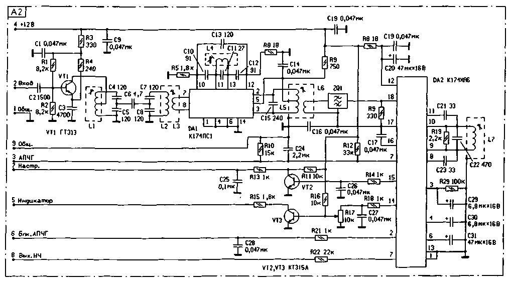
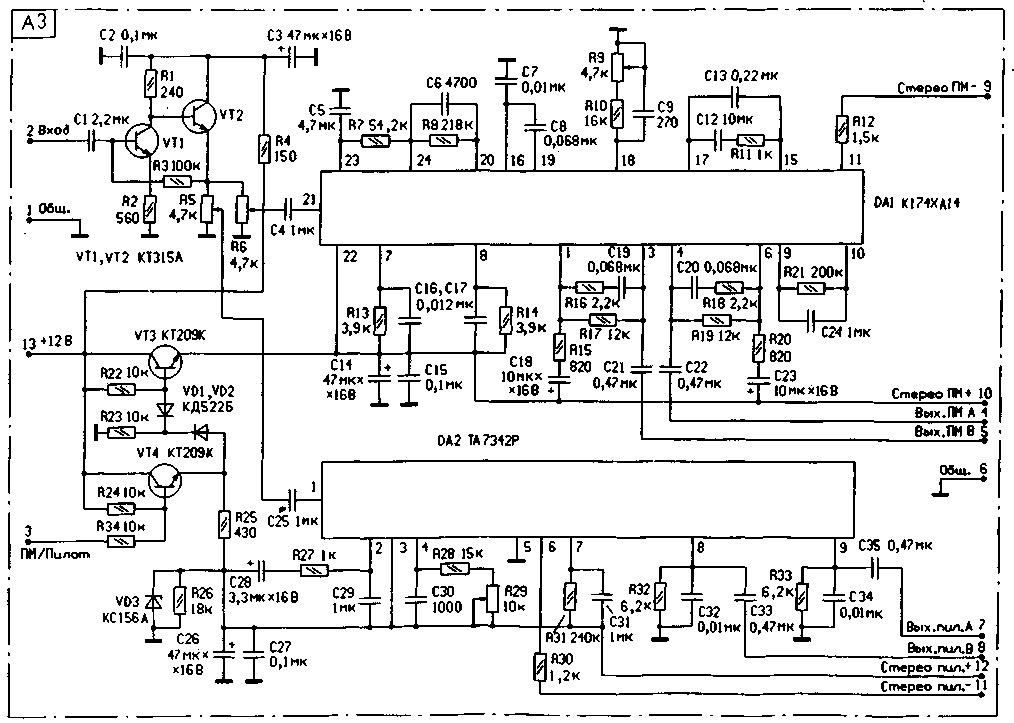
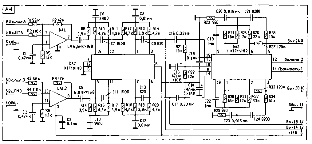
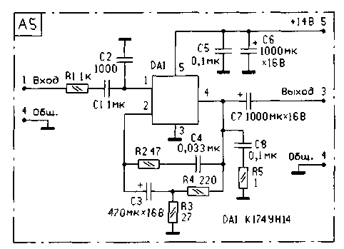
Encyclopedia of radio electronics and electrical engineering / radio reception Broadcasting in the VHF bands makes it possible to provide radio listeners with a higher quality of the sound signal in comparison with broadcasting in the long, medium and short wave bands. Moreover, the struggle for the quality of reception has led to the emergence of industrial and amateur radio receivers exclusively for reception in the VHF bands. Readers are invited to one of these amateur developments. And although the author calls his construction complex, we are not inclined to dramatize the assessment. Let's just say that improving the quality of work (good stereo in two formats of the standard) also requires certain costs. The described design of the receiver is intended for listening to broadcasting stereo and monophonic VHF-FM radio stations in the range of 65,8 ... 74 MHz and 88 ... It is possible to receive stereo programs with both polar modulation and pilot tone. The receiver's memory can be pre-programmed for 55 radio stations and, if necessary, quickly select any of them using the remote control or directly with the buttons on the receiver's front panel. Volume and stereo balance are also adjustable both remotely and from the control panel. The received channel number and all the necessary information during tuning is displayed on a two-digit seven-segment display. The proposed design is an attempt to create an easy-to-use device suitable for high-quality stereo reception in an area with a large number of television and VHF-FM radio stations. Despite the relatively complex circuitry, the receiver is easy to set up and operate. It is assembled from available parts and consists of several functionally completed blocks assembled on separate boards. This allows you to easily make any changes and additions to it when repeating the design. The receiver is made according to the scheme with double frequency conversion. The signal received by the antenna is converted into the first IF by a standard television channel selector of the SK-V-418-8 type. You can also use SK-V-41 or any imported one, designed to work in the MB, UHF and CATV (cable television) bands 110,..174 MHz. It is not recommended to use outdated selectors like SKM-24, since they do not cover the range of 100 ... 108 MHz and have a lower gain. As you know, any superheterodyne receiver, in addition to the main channel, also has out-of-band reception channels at the mirror and intermediate frequencies, as well as due to the conversion of the local oscillator oscillation frequency to harmonics and subharmonics, i.e. reception on frequencies fnp=mfg ± nfc, where m, n = 1, 2, 3... ; fnp - intermediate frequency; fg - local oscillator frequency; fc - signal frequency. The receiver has two local oscillators, so there are even more out-of-band channels in it, since local oscillator signals can interact with each other on non-linear elements of the device. Of course, the vast majority of these side channels are filtered out by the channel selector input circuits and the first and second IF bandpass filters. However, the frequency of the local oscillator and the IF is still recommended to be chosen so that the combination frequencies are not in the frequency range of the useful signal. In other words, so that there are no affected points near the radio stations received in the area. This is achieved by choosing the value of the first IF, which should lie within the frequency range of 32,5 ... 38 MHz. In the author's version, the first IF is 32,8 MHz (IF1). From the output of the channel selector, the IF1 signal is fed to the input of the IF-FM block (A2). Its scheme is shown in Fig.1. After cascade amplification on VT1 and a double-circuit bandpass filter L1 - L3, C4 - C8, the signal is fed to the second frequency converter, made on the DA1 chip. A local oscillator with an oscillatory circuit on L4, C10 - C 13 operates at a frequency of 22,1 MHz. The second IF is standard - 10,7 MHz (IF2). It is allocated on the L5C15 circuit, passes through the main selection filter ZQ1 and enters the input of the DA2 multifunctional microcircuit. The filter must have a bandwidth of 250...300 kHz. You can use a concentrated selection filter like FP1P-0496 or some imported one. The OD2 chip is included according to a typical scheme and performs the main amplification, limitation and demodulation. In addition, it generates an AFCG voltage and a tuning signal ("Adjust") supplied to the control unit. Upon receiving this signal, the control unit slows down the tuning speed of the receiver to facilitate fine presetting to the station. From the control unit to pin 2 of the DA2 microcircuit, the signal "Blk. APCG" comes, which turns off the APCG for the time the receiver is tuned. The demodulated low-frequency signal from pin 7 of the DA2 chip through the resistor R22 is fed to the input of the stereo decoder block (A3). The scheme of this block is shown in fig. 2. A preamplifier is assembled on transistors VT1, VT2. The tuned resistors R5 and R6 are designed to select the optimal input signal level for the DA2 and DA1 stereo decoder chips, respectively. A stereo decoder for a signal with polar modulation according to the 01 RT system (frequency range 65,8 ... 74 MHz) is made on a DA1 chip of the K174XA14 type. It is not recommended to use the more modern K174XA35 development, since in real signals it works very unstable, with very noticeable clicks and constantly switches from the "Stereo" mode to the "Mono" mode. The stereo decoder on the K174XA14 chip works much more stable. It is assembled according to the scheme described in detail in [1]. A stereo decoder for a signal with a pilot tone according to the CCIR system (frequency range 88 ... 108 MHz) is assembled on a DA2 chip of the TA7342R type, also according to a typical scheme. Switching of stereo decoders is carried out by the "PM / Pilot" signal supplied from the control unit. At a high level of this signal, the transistor VT3 is open, and the transistor VT4 is closed and the supply voltage is applied to the DA1 chip. When the signal is low, power is supplied to the DA2 chip and disconnected from the DA1 chip. Both microcircuits used have an automatic built-in Mono-Stereo switch, so forced activation of the Mono mode is not provided. To switch to this mode, simply turn on the "wrong" Stereo Decoder. For example, to receive a station operating on a polar modulation system in monaural mode, you need to turn on the Stereo Decoder for the pilot tone system. Of course, by somewhat complicating the diagram of the A3 block, it is possible to implement the forced inclusion of "Mono". However, as practice has shown, this is not necessary. The output signals of the stereo decoders are fed to the input of the filter unit and the A4 electronic volume control. Its scheme is shown in Fig. 3. A preamplifier is assembled on the DA1 K548UN1 chip. Its purpose is to normalize the levels of signals from the outputs of stereo decoders. As DA1, it is permissible to use any low-noise op amp in standard inclusion. An active filter for suppressing the residual subcarrier frequencies of a complex stereo signal is assembled on the DA2 chip. In the absence of the K174UN10 microcircuit, the filter can be assembled according to any other scheme, for example, as recommended in [2]. The electronic volume and stereo balance control is assembled on the DA3 chip of the A4 block according to a typical scheme. The control voltage is supplied to terminals 13 and 12 of this microcircuit from the control unit. The signal from the outputs "Out. 1A" and "Out. 1B" is fed to an external connector for recording on a tape recorder. Its level is independent of the volume control. From the outputs "Out. 2A" and "Out. 2V" the signal is fed to the power amplifier and to the connector intended for connecting an external high-quality terminal ULF. The receiver power amplifier (A5) is made on the K174UN14 chip. It doesn't have any special features. The diagram of one channel of the amplifier is shown in fig. four.
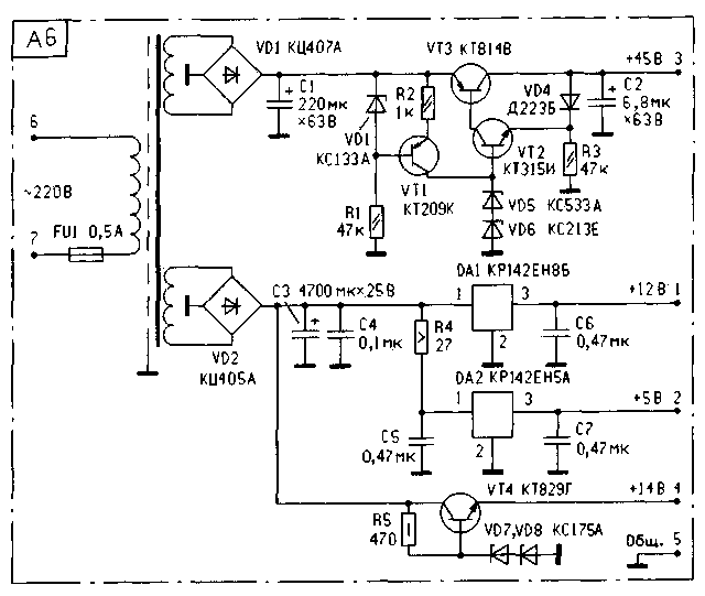
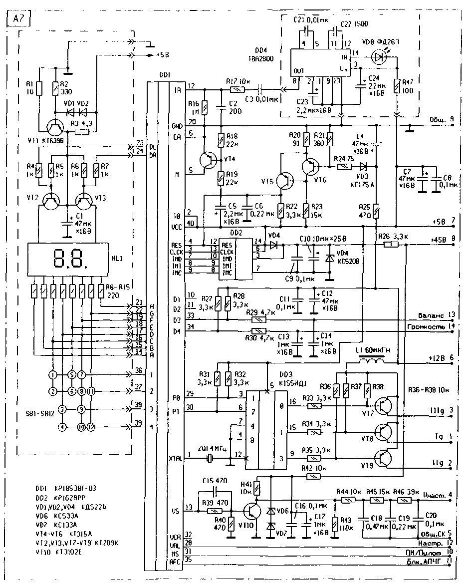
The power supply (A6) is assembled according to the transformer circuit, its circuit is shown in fig. 5. The receiver control unit (A7) is made on the basis of the "television" controller KR1853VG1-03. Its scheme is shown in Fig. 6. Basically, it repeats the scheme of the CH-44 tuning system for domestic TVs of the 4th generation. The differences are in the exclusion of the standby mode and in the range decoder circuit. The decoder is made on a DD3 chip and transistors VT7 - VT9. The need for such a complication of the circuit is explained by the fact that in the controller the rate of change of the setting voltage is different in different ranges. The radio signal occupies a much smaller frequency band than the television signal, so the frequency of tuning in the range should be less. In the proposed scheme, range 1-2 of the controller is not used, range 3 corresponds to the frequency band 50 ... 100 MHz, range 4-5 - 100 ... 230 MHz, and range H - UHF. The ranges are displayed on the indicator as shown in Fig. 7: a) - voltage at the lower end of the range 50 ... 100 MHz; b) - in the center of the range 100 ... 230 MHz; c) - at the upper end of the UHF range. The upper dashes of the indicator are used in the mode for a three-level display of the tuning voltage. The block of indicators HL1 has a circuit for connecting elements with a common anode, any type of indicator, for example, KIPTs09I-2/7K.
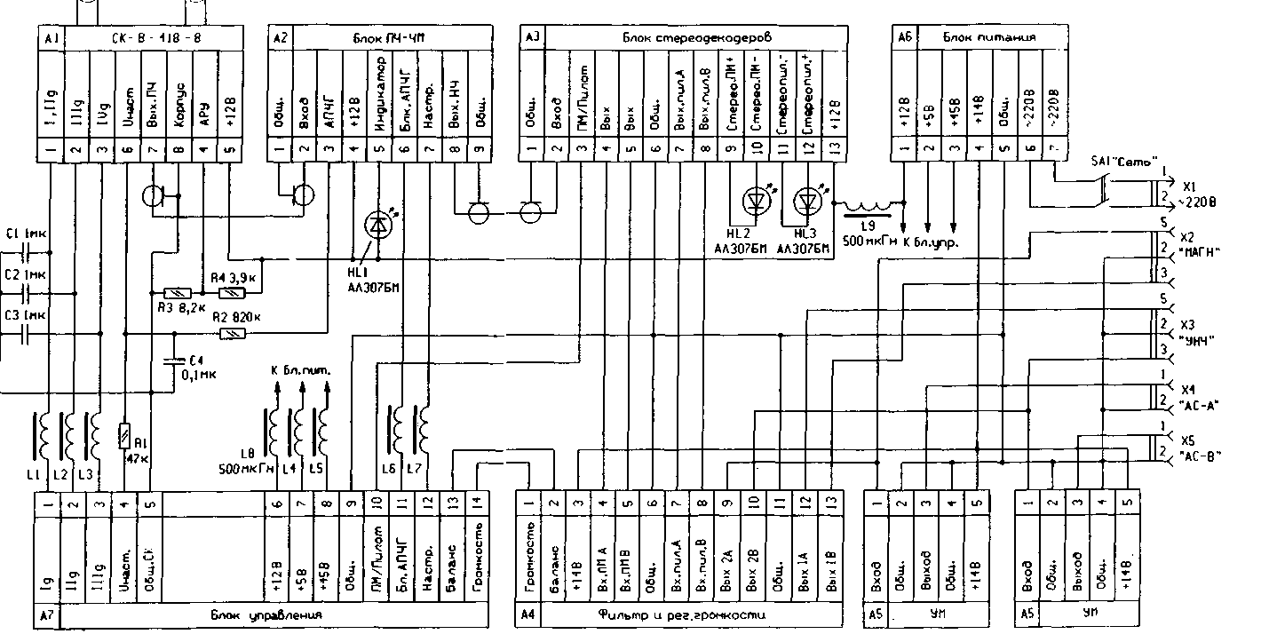
For remote control, a standard remote control PDU-44 (RC-401) from 4th generation TVs is used. This remote control is based on the ITT IRT1260 chip, which has a domestic counterpart KR1056KhL1. The purpose of the buttons on the local keyboard is given in the table. The corresponding remote control buttons perform a similar function. The temperature coefficient of the zener diodes VD6 and VD7 (see Fig. 6) determines the stability of the receiver tuning. In the author's version, the best thermal compensation of the local oscillator frequency was obtained using four zener diodes connected in series - two D814B and two KS191F. The KR1853VG1-03 microcircuit is an analogue of the SAA1293A-03 from ITT, KR1628RR2 - MDA2062, the TVA2800 IR remote control input amplifier has domestic analogues KR1054UI1, KR1054KHAZ, KR1056UP1, KR1084UI1. Pin numbers in fig. 6 are shown for KR1628PP2 and TVA2800 microcircuits in a 14-pin package. For a 16-pin package, the numbers of pins from the 8th to the 14th should be increased by 2. Buttons SB1 - SB12 - for short circuit without fixation. The interconnection diagram of the receiver is shown in fig. eight. Inductors L1 - L7 are ferrite tubular magnetic cores put on the corresponding conductors. You can use magnetic circuits made of F600 ferrite from DM-0,1 chokes. DM-8 with an inductance of 9 μH was used as chokes L0,1 and L500. LEDs HL1 - HL3 are located on the front panel of the receiver, HL1 indicates tuning to the station, and HL2 and HL3 - the presence of a stereo signal on a system with polar modulation and pilot tone, respectively. Elements C1 - C4, R1 - R4, L1 - L9 are mounted on the terminals of blocks A1, A5 and A7. Connectors X2 and X3 of the ONTS-KG-4-5/16-R type are designed to connect the inputs of a tape recorder and an external UMZCH, respectively. They are located on the back of the receiver. UX1 is also located there for connecting the power supply of 220 V and X4, X5 for connecting the acoustic systems of channels A and B. This design is designed to be repeated by sufficiently qualified radio amateurs, therefore, drawings of printed circuit boards are not given. When placing parts on boards, it is necessary to adhere to the general rules for mounting high-frequency structures. Inside the case, the board should be placed in such a way that the channel selector and the IF-FM unit are at the maximum distance from the control unit. Regulating transistors and microcircuits of stabilizers and power amplifiers must be fixed on the radiator as far as possible from the high-frequency blocks and the stereo decoder block. All loop coils in the IF-FM unit are wound with 0,28 mm PEV wire on frames with a diameter of 7 mm with trimmers made of F100 ferrite. Such frames were used in the contours of the KB bands of the OCEAN receiver. The communication coils are wound with 0,1 mm PEV wire over the corresponding loop coils. All oscillatory circuits are enclosed in brass or aluminum screens. Number of coil turns: L1 - 3+3, L2 - 6, L3 - 3, L4 - 10, L5 - 6+6, L6 - 5, L7 - 6. The elements of the block of stereo decoders C6, R7, R8, according to the reference data for the K174XA14 chip, must be selected with an accuracy of ± 1%, but without much damage to the quality, it is quite possible to use the nearest standard value. Capacitor C12 is non-polar. If there is no capacitor of the required capacity, it can be made up of three K10-47 (option a).
Capacitors C9 and C30 determine the VCO frequency of the microcircuits, so they should be with the lowest possible TKE. Of the old types, KSO-G can be recommended. There are no special requirements for other elements of the block. The adjustment of the A2 IF-FM block has no special features and is carried out according to the standard method. Capacitor C9 must be soldered directly to terminals 12 and 1 of the K174XA6 microcircuit from the side of the printed conductors. Establishing the A3 stereo decoder unit consists in adjusting the VCO frequency with resistors R9 and R29 until the frequency is reliably captured by the subcarrier PLL system of microcircuits. This moment is determined by the ignition of the HL2 or HL3 LED. Resistors R5 and R6 achieve the same level of signals at the output of stereo decoders. In the control unit, you must set the options in the non-volatile memory DD2. This is done in the service mode only with the remote control. To enter this mode, you must press and hold the "SERVICE" button on the remote control for 0,5 s. After the symbols "CH °" appear on the indicator, release and press this button again. After the symbols "OP" appear, you need to select the option number on the left indicator using the "Volume +" or "Volume -" key, and then set or reset the corresponding option bits on the right indicator using the numeric keys of the remote control.All the necessary settings are shown in Fig. 9.
After programming each option byte, press the "MEMORY" key on the remote control to write information to non-volatile memory. Presetting to radio stations is similar to tuning a 4th generation TV with the CH-44 tuning system. First you need to select the band using the "BAND" button, then use the "SETUP+" or "SETUP-" button on the remote control or local panel to tune in to the desired station, and select the appropriate system using the "PM / Pilot" button. At the same time, the indicator starts flashing. The inclusion of a stereo decoder for a system with polar modulation is indicated by a luminous dot on the right familiarity of the indicator. Then, using the "PROGRAM-" or "PROGRAM+" button, select the channel number for the station in the range from 1 to 55. You can also use the numeric keys of the remote control. To memorize the information, you must press the "MEMORY" key, while the indicator stops flashing. In the future, tuning to the programmed stations is carried out by going through the channels in the direction of increasing or decreasing with the "PROGRAM+" or "PROGRAM-" button, respectively. With the remote control, it is possible to directly enter the channel number with the numeric buttons. The position of the volume and stereo balance controls is also stored in non-volatile memory when the "MEMORY" button is pressed. The operation of the KR1853VG1-03 controller and the setup procedure are described in more detail in [3] and [4]. The total consumption from sources +5 V, +12 V, +14 V is not more than 0,6 A, and from a source of +45 V - 0,05 A. Literature
Author: I. Khlyupin, Dolgoprudny, Moscow Region; Publication: N. Bolshakov, rf.atnn.ru
Artificial leather for touch emulation
15.04.2024 Petgugu Global cat litter
15.04.2024 The attractiveness of caring men
14.04.2024
▪ Phone at a pedestrian crossing - illegal ▪ Canon XEED 4K4Z Compact 600K Projector ▪ Synthesized a new form of carbon ▪ CC3200+CC2650 Wireless Gateway Connects BLE Sensors to the Internet
▪ section of the site Labor protection. Selection of articles ▪ article Logarithms. History and essence of scientific discovery ▪ article Which movie made Iggy Pop and Tom Waits start smoking again? Detailed answer ▪ article The functional composition of Brandt TVs. Directory ▪ article Mordant for wooden smoking pipes. Simple recipes and tips ▪ article Adjustable stabilizer option. Encyclopedia of radio electronics and electrical engineering
Home page | Library | Articles | Website map | Site Reviews www.diagram.com.ua |


 Arabic
 Bengali
 Chinese
 English
 French
 German
 Hebrew
 Hindi
Hindi Italian
 Japanese
 Korean
 Malay
Malay Polish
 Portuguese
 Spanish
 Turkish
 Ukrainian
 Vietnamese


 Leave your comment on this article: