Battery voltage stabilizer. Encyclopedia of radio electronics and electrical engineering

Encyclopedia of radio electronics and electrical engineering / Surge Protectors
 Comments on the article
When powering amateur radio equipment from a rechargeable battery, the problem is that its voltage decreases as it discharges, the output power of the transceiver decreases markedly, and when the supply voltage is less than 11 V, it stops working altogether. The German radio amateur Georg Tief (DK2GT) tried to solve this problem. He described his stabilizer, which ensured continuous operation of the transceiver for 10 hours in the field, in the July 2009 issue of CQ DL (Tief G. Dreifacher Step-Up-Wandler. Stabile Spannungen fur den FieldDay).
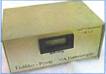
To maintain a stable supply voltage of the transceiver, he used a switching step-up voltage regulator, consisting of three identical blocks connected in parallel at the inputs and outputs. Each of them is designed for a load current of 10 A, and together they give 30 A, which is quite enough to power a 100 W transceiver. The impulse principle of stabilization ensured a high efficiency of the device, which is important for autonomous battery power.
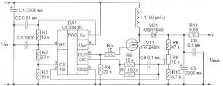
Fig. 1
On fig. 1 shows a diagram of one of the three channels of the stabilizer. It consists of low cost available components included mostly 100W power. The impulse principle of stabilization ensured a high efficiency of the device, which is important for autonomous battery power.
Transistor VT1 and diode VD1 are equipped with heat sinks. It should be noted that even at full load, the transistor VT1 heats up slightly. The main heat source is the VD1 diode, it is he who needs a larger heat sink. With the help of a tuning resistor R9, the output voltage can be changed within 12 ... 16 V. The storage inductor L1 requires special attention, the reliability and efficiency of the device depend on its quality. If the material of the magnetic core is chosen incorrectly, its saturation with the most severe consequences is possible. The author used Amidon T106-26 toroidal magnetic circuits made of carbonyl iron, wound on them with 25 turns of insulated copper wire with a diameter of 1,5 mm.
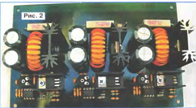
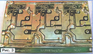
These chokes and other elements are clearly visible in the photograph of the stabilizer board in the top view (Fig. 2). And the bottom view (Fig. 3) shows what the printed wiring of the block looks like. The printed conductors connecting the stabilizers to each other, through which a large current flows, are reinforced with stranded copper wires of a large cross section.
The difference in the output voltages of the channels leads to the fact that with a relatively small load current, only one channel actually works. As the load grows, the rest are connected, but the total current is distributed unevenly between them.
To minimize this effect, equalizing resistors are required - R11 and similar ones in other channels with a resistance of 0,05 ohms (two 0,1 ohm resistors can be connected in parallel). Before soldering them into the board, apply an input voltage to the assembled unit and set the output voltages of the channels equal to the specified voltage (usually 13,5 V) with a mutual difference of no more than 0,1 V using trimmer resistors.
After completing this operation, the equalizing resistors can be soldered into place and the stabilizer can be put into operation.
It must be taken into account that since the proposed regulator is a step-up regulator, it cannot maintain the output voltage stable if the input voltage is equal to or greater than its specified value. Under these conditions, the transistor VT1 remains permanently closed and the input voltage through the inductor L1, the diode VD1 and the resistor R11 is continuously supplied to the output.
The minimum input voltage is limited by the fact that in order to start the UC3843N microcircuit, it is necessary to apply a voltage of at least 8,5 V to it. And when it is subsequently reduced to 7,6 V, the microcircuit is turned off.
The rated voltage of oxide capacitors C1 and C5 is not indicated in the original article. It is recommended to use capacitor C5 for a voltage of at least 35 V, since with the values \u9b\u33bof the elements indicated in the diagram, the trimming resistor R9 can bring the output voltage to almost 10 V. To regulate this voltage within the limits indicated in the article, you should swap the values of resistors R4,7 and R10. The first of them should be XNUMX kOhm, and the second - XNUMX kOhm.
Publication: radioradar.net
 See other articles Section Surge Protectors.
Read and write useful comments on this article.
<< Back
 Latest news of science and technology, new electronics:
Artificial leather for touch emulation
15.04.2024
In a modern technology world where distance is becoming increasingly commonplace, maintaining connection and a sense of closeness is important. Recent developments in artificial skin by German scientists from Saarland University represent a new era in virtual interactions. German researchers from Saarland University have developed ultra-thin films that can transmit the sensation of touch over a distance. This cutting-edge technology provides new opportunities for virtual communication, especially for those who find themselves far from their loved ones. The ultra-thin films developed by the researchers, just 50 micrometers thick, can be integrated into textiles and worn like a second skin. These films act as sensors that recognize tactile signals from mom or dad, and as actuators that transmit these movements to the baby. Parents' touch to the fabric activates sensors that react to pressure and deform the ultra-thin film. This ... >>
Petgugu Global cat litter
15.04.2024
Taking care of pets can often be a challenge, especially when it comes to keeping your home clean. A new interesting solution from the Petgugu Global startup has been presented, which will make life easier for cat owners and help them keep their home perfectly clean and tidy. Startup Petgugu Global has unveiled a unique cat toilet that can automatically flush feces, keeping your home clean and fresh. This innovative device is equipped with various smart sensors that monitor your pet's toilet activity and activate to automatically clean after use. The device connects to the sewer system and ensures efficient waste removal without the need for intervention from the owner. Additionally, the toilet has a large flushable storage capacity, making it ideal for multi-cat households. The Petgugu cat litter bowl is designed for use with water-soluble litters and offers a range of additional ... >>
The attractiveness of caring men
14.04.2024
The stereotype that women prefer "bad boys" has long been widespread. However, recent research conducted by British scientists from Monash University offers a new perspective on this issue. They looked at how women responded to men's emotional responsibility and willingness to help others. The study's findings could change our understanding of what makes men attractive to women. A study conducted by scientists from Monash University leads to new findings about men's attractiveness to women. In the experiment, women were shown photographs of men with brief stories about their behavior in various situations, including their reaction to an encounter with a homeless person. Some of the men ignored the homeless man, while others helped him, such as buying him food. A study found that men who showed empathy and kindness were more attractive to women compared to men who showed empathy and kindness. ... >>
| Random news from the Archive Mobile phone base for $20
27.09.2005
The German company Infineon Technologies AG has announced the ULC platform for mobile phones.
Development costs only $20 and is almost a finished cell phone. Judge for yourself: there is a keyboard, display and charging system, as well as software for simple functions and SMS support.
Motorola and Philips have already announced that they plan to create an inexpensive mobile phone based on the new platform. It seems that now everyone will have a cell phone. After all, so far, according to statistics, 3,5 billion people cannot afford to buy such a necessary device.
The difference between the Infineon platform and the existing ones is that it contains less than a hundred electronic components, while in more complex models there are from 150 to 200. The processor, the transmitting and receiving electronics are installed on board the novelty. And this means that there is no need for numerous filters, resistors and capacitors.
The size of the ULC is three times smaller than similar modern developments - only 30x30 mm. As a result of the small size of the platform, it is possible to install a high-quality battery, such as nickel-metal hydride (NiMH).
In 2010, 150 million mobile phones priced under $50 will be sold, according to a US analyst firm.
|
Other interesting news:
▪ extreme hardening
▪ Nokia 330 with navigator
▪ Potato plastic
▪ Butterfly saves not the pattern of eyes on the wings
▪ Ecology and the Internet
News feed of science and technology, new electronics
 Interesting materials of the Free Technical Library:
▪ section of the site Lecture notes, cheat sheets. Selection of articles
▪ article All in the past. Popular expression
▪ article In what magical film, released before the books of J.K. Rowling, does the main character Harry Potter act? Detailed answer
▪ Anchar article. Legends, cultivation, methods of application
▪ article Windshield wiper cycle regulator. Encyclopedia of radio electronics and electrical engineering
▪ article A million to one. Focus secret
Leave your comment on this article:
 All languages of this page
Home page | Library | Articles | Website map | Site Reviews

www.diagram.com.ua
2000-2024


 Arabic
 Bengali
 Chinese
 English
 French
 German
 Hebrew
 Hindi
Hindi Italian
 Japanese
 Korean
 Malay
Malay Polish
 Portuguese
 Spanish
 Turkish
 Ukrainian
 Vietnamese