|
|


 Arabic
 Bengali
 Chinese
 English
 French
 German
 Hebrew
 Hindi
Hindi Italian
 Japanese
 Korean
 Malay
Malay Polish
 Portuguese
 Spanish
 Turkish
 Ukrainian
 Vietnamese
|
ENCYCLOPEDIA OF RADIO ELECTRONICS AND ELECTRICAL ENGINEERING Battery protection for the emergency lighting system. Encyclopedia of radio electronics and electrical engineering
Encyclopedia of radio electronics and electrical engineering / Protection of equipment from emergency operation of the network, uninterruptible power supplies The emergency power supply system for LED lamps can be organized on the basis of any common computer uninterruptible power supply (UPS), powering the lamps from the 12 V battery present in it. Constant recharging of the battery with a working 220 V network will be provided by the means of the UPS itself. However, in order to avoid damage and premature failure of the battery, it is advisable to connect the load (luminaires) to it through the protection devices described below. These devices are simple and built on readily available parts. Although the author made them in the form of separate structures, they may well be placed in the case of many UPSs.
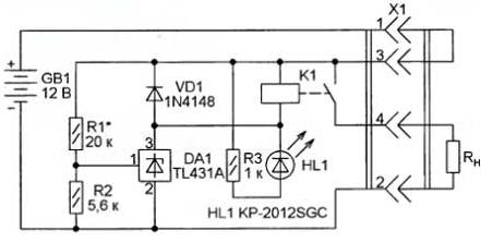
The simplest device, the circuit of which is shown in Fig. 1, protect the battery from deep discharge. The battery voltage GB1, below which the output circuit of the parallel stabilizer DA1 opens, is set by a voltage divider connected to the control input of the stabilizer from resistors R1 and R2. With the values of the resistors indicated in the diagram, a threshold of about 11,5 V is set, which prevents deep discharge of the battery. Its load (RH) can be any electrical appliances designed to be powered by a constant voltage of 12 V with a current consumption of not more than 750 mA. For example, LED lamps. The switch, as a separate element, is not provided in the device. Its power circuit is closed by a jumper between pins 1 and 3 of the counterpart of connector X1, with which the load is connected. If the battery voltage is above the permissible minimum, relay K1 is activated, connecting the RH load with its contacts. At the same time, the HL1 LED signaling this turns on. As soon as the battery voltage drops below the permissible value, as a result of which the voltage between pins 1 and 2 of the DA1 stabilizer drops below 2,5 V, the relay winding circuit opens, it disconnects the load, and the LED goes out.
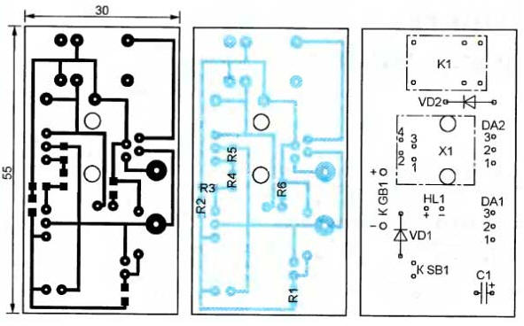
The device is mounted on a single-sided printed circuit board, shown in fig. 2. It is designed to accept surface mount resistors, TJ5-6P4C phone jack and WJ102H-1C-12VDC relay. The dimensions of the board allow it to be installed in a standard two-gang telephone jack housing. The TL431A parallel stabilizer can be replaced with TL431C or KR142EN19A, but in the latter case, a relay with a winding operating current of not more than 100 mA should be used. For TL431 series stabilizers, current up to 150 mA is allowed.
If the device described above is supplemented with a timer, as shown in Fig. 3, the load (emergency lighting) will only be connected for a limited time, which will save battery power. The timer is made on a parallel stabilizer DA1. When the power is turned on, the charging of the capacitor C1 through the resistor R2 begins. Until the voltage on the capacitor and the control input of the stabilizer DA1 reaches 2,5 V, the output circuit of this stabilizer is closed. The deep discharge protection unit on the DA2 stabilizer during this period of time works in exactly the same way as described above. But as soon as the exemplary voltage of the DA1 stabilizer is exceeded, it will bypass the resistors R4 and R5. The voltage at the control input of the stabilizer DA2 will drop below the reference voltage and the load from the battery will be turned off. The time until automatic load shedding depends on the time constant of the R2C1 circuit and can be up to several minutes. At any time, by pressing the SB1 button, you can discharge the capacitor C1 and thereby restart the timer. Diode VD1 is designed to quickly discharge the capacitor after disconnecting the counterpart of connector X1.
On fig. 4 shows the printed circuit board of this version of the device. The use of the KR1EN142A stabilizer as DA19 in this case is highly undesirable. The higher control current compared to the TL431 series stabilizers will lead to the need to reduce the value of the resistor R2, which will also reduce the timer exposure.
If it is required to protect the battery not only from excessive discharge, but also from exceeding the load current, the circuit of the original version of the device (see Fig. 1) can be supplemented with a current protection unit, as shown in Fig. 5. As soon as the voltage drop across the resistor-current sensor R8 connected in series with the load reaches the opening voltage of the transistor VT1, the transistors VT2, VT3 will also open, forming an analogue of the trinistor. In this case, the voltage at the control input of the stabilizer DA1 will drop below the reference input, the relay winding K1 will be de-energized, and the load will be disconnected by the open relay contacts. Due to the positive feedback that covers the SCR analog transistors, the device will remain in this state even after the relay is released. To re-apply voltage to the load, you will have to undock the mating part from the X1 connector and reconnect it.
The printed circuit board of this version of the device is shown in fig. 6. Resistor R6 to provide the desired power dissipation is made up of four 3 kΩ resistors connected in parallel. It is permissible to replace BC847A transistors with any of this series or domestic KT3130 series, and BC857A with any BC857 or KT3129 series. Surface mount transistors can also be replaced with the usual KT3102 and KT3107 series, but this will require reworking the printed circuit board. In all three versions of the device, in addition to the LEDs indicated in the type diagrams, many others can be used. It is worth noting that when powering devices with a rated supply voltage of 3 ... 9 V from a 12 V battery, it should be lowered to the desired value using a switching, rather than a linear, stabilizer. Significantly higher efficiency of the pulse stabilizer will provide a longer duration of operation of the device in emergency conditions. Author: I. Tsaplin
Machine for thinning flowers in gardens
02.05.2024 Advanced Infrared Microscope
02.05.2024 Air trap for insects
01.05.2024
▪ The first Americans were Japanese ▪ Scientists brought together identically charged particles
▪ section of the site Microphones, radio microphones. Article selection ▪ article Steps of a sazhen. Popular expression ▪ article What will be the biggest killer of humanity by 2030? Detailed answer ▪ article Chemical analysis laboratory assistant. Standard instruction on labor protection ▪ article Extender-carrier. Encyclopedia of radio electronics and electrical engineering ▪ article Hypnotized box of matches. Focus Secret
Home page | Library | Articles | Website map | Site Reviews
www.diagram.com.ua |


 Leave your comment on this article: