|
|


 Arabic
 Bengali
 Chinese
 English
 French
 German
 Hebrew
 Hindi
Hindi Italian
 Japanese
 Korean
 Malay
Malay Polish
 Portuguese
 Spanish
 Turkish
 Ukrainian
 Vietnamese
|
ENCYCLOPEDIA OF RADIO ELECTRONICS AND ELECTRICAL ENGINEERING Power supply for the M890G multimeter. Encyclopedia of radio electronics and electrical engineering
Encyclopedia of radio electronics and electrical engineering / Power Supplies The weak point of some portable digital multimeters is, as you know, a 6F22 nine-volt battery, which does not last long with frequent use of the device. This forces radio amateurs to look for alternative power sources for the device. To date, many designs have been developed and described in the literature, which are step-up voltage converters powered by Li-Ion batteries [1-3]. The devices described in these articles are of interest for repetition, although they are not without drawbacks. So, the converter [1] has a rather low efficiency, which is due to the presence of a parametric stabilizer. The converter presented in [2] also (and for the same reason) is not very efficient and, moreover, does not have a timer. The proposed version of the converter (its circuit is shown in Fig. 1) is also powered by a lithium-ion battery and is free from the mentioned disadvantages. It is made according to the scheme of a step-up switching stabilizer. The device is based on a multivibrator based on transistors of different structures, similar to that used in [2], but with output voltage stabilization. This allows you to increase the load capacity of the converter and its efficiency, and also gives it another useful property - the ability to control the degree of battery discharge. The multivibrator is assembled on transistors VT1, VT3. When the latter is closed, pulses appear on its collector, they are rectified by the VD1 diode, the capacitor C3 smoothes the rectified voltage.
Stabilization of the output voltage of the converter is carried out as follows. As soon as it exceeds a certain value, the zener diode VD2 opens, a positive voltage is applied to the base of the transistor VT1 and it starts to close. This leads to a decrease in the frequency of the converter, and as a result, the output voltage. If the output voltage drops below a certain value, the transistor, on the contrary, opens and it increases. In this case, the efficiency of the converter is higher than with a subsequent linear stabilizer. It should be noted that the VD2 zener diode operates in low current mode, so its stabilization voltage may be less than indicated in the technical specifications. You can change the output voltage of the converter by selecting a zener diode, as well as resistor R4. It is easy to see that the output voltage of the converter stabilizes relative to the positive terminal of the battery, therefore it depends on the degree of charge of the latter. In my case, at a battery voltage of 4,2 V, it is 9 V, and at a voltage of 3,1 V, it is about 7 V, at which most multimeters display a low battery symbol. This allows the battery to be charged in a timely manner. In case they forget to turn off the device, the converter is equipped with a timer on the VT2 transistor. It is controlled by buttons SB1 ("On" - "Enable") and SB2 ("Off" - "Off"). Despite its simplicity, the timer has rather steep switching fronts. It works as follows. In the initial state, the capacitor C2 is charged almost to the battery voltage, and the gate voltage of the transistor VT2 is zero, and it is closed. When the contacts of the button SB1 are closed, the capacitor quickly discharges through the resistor R6 and the opening voltage is supplied to the gate VT2 from the output of the converter. The converter starts up, and its output voltage increases, opening the VT2 transistor even more. After releasing the button, the capacitor C2 begins to charge through the resistor R5. As the capacitor charges, the voltage across the resistor R5, and consequently, at the gate of the transistor VT2, decreases. At some point, it decreases so much that the transistor begins to close. In this case, the voltage at the output of the converter decreases, which, in turn, causes the transistor to close even more. Through the time-setting capacitor, the POS circuit is closed, accelerating the switching of the transistor. With the transistor indicated on the diagram and the values \u5b\u2bof resistor R12 and capacitor C7, the timer exposure time is about 3,1 minutes at an output voltage of the converter of 9 V (on the battery, respectively, 15 V). With an output voltage of XNUMX V, this time is about XNUMX minutes. With other transistors, the operating time of the device may differ. The timer has one feature: if the output voltage of the converter drops sharply, caused by an overload or a short circuit, the timer may turn off. However, this is possible only in one case, namely, when measuring the current transfer coefficient of transistors, if a transistor with a broken collector-emitter section or the wrong structure is inserted into the test panel. It should be noted that this disadvantage only becomes apparent when the timer has already expired. All parts of the converter, except for buttons and resistors R1 and R6, are installed on a printed circuit board made of fiberglass laminated on one side (Fig. 2). To reduce the level of interference, it is enclosed in a screen made of tinned sheet 0,5 mm thick (you can use the case of an unusable 6F22 battery). The shield is connected to the negative terminal of the battery. Buttons SB1 and SB2 are mounted on a separate printed circuit board (Fig. 3), which is placed in a convenient place in the device.
A little about the details. The converter uses MLT resistors, all capacitors are imported. The field-effect transistor can also be replaced with another one, for example KP501A, but it is better to use a powerful switching one (for example, IRLML004 or NTD3055), however, for this you will have to change the configuration of the corresponding conductors of the printed circuit board. The lower the threshold voltage at the gate and the drain-source resistance in the open state, the better. We will replace the bipolar transistor KT209B (VT1) with any of the KT3107 series, and KT3102EM (VT3) with a 2SC945 transistor. Instead of a KS156A (VD2) zener diode, you can use an imported one, for example BZV55C5V6, or a zener diode with a different stabilization voltage, for example, 5,1 or 6,2 V, but in this case you will also have to select the R4 resistor. Schottky diode SR160 (VD1) will be replaced by BAT48. Inductor L1 contains 150 turns of PEV-2 0,18 wire, wound on an annular magnetic circuit of size K10x6x3 from the electronic ballast of a faulty CFL, after winding it is impregnated with KhV-784 varnish. In some CFLs, suitable chokes are installed at the input of the mains rectifier - you can try using one of them. I recommend setting up the converter when powered from a laboratory source with a current limit of 100 ... 150 mA, since such generators are prone to "falling asleep", especially when starting under load. With serviceable parts and error-free installation, the adjustment of the device is reduced to the selection, if necessary, of the resistor R4 to set the output voltage to 7 V at the maximum load current and supply voltage of 3,1 ... 3,2 V. It is best during the adjustment instead of resistors R3 and R4 turn on a trimmer with a resistance of 10 ... 15 kOhm. It is necessary to find such a position of its engine, in which the voltage of the converter does not drop much in any mode of operation of the device, and it starts up steadily at full load and any voltage (from 3 to 4,2 V) of the battery. Then, having measured the resistance between the engine and the terminals of the resistive element of the tuning resistor, you should install fixed resistors of the closest ratings on the board. You can try to increase the efficiency of the converter by selecting the inductor L1 and the frequency of the generator. Really achievable efficiency can be more than 70%. When setting up the converter, it should be borne in mind that if the VD2 zener diode circuit is accidentally interrupted or disconnected, the voltage at the converter output may increase to more than 25 V, which will lead to the failure of the VT2 transistor and the multimeter! To prevent this from happening, a zener diode with a stabilization voltage of 12 ... 14 V should be connected in parallel with the output of the converter (not shown in the diagram). After adjustment, the board is covered with two layers of XB-784 varnish. In addition to protecting the device from moisture, this varnish also glues oxide capacitors and a choke to it. It should be remembered that this varnish is electrically conductive, so you can turn on the converter coated with it only after it has dried (at room temperature this will take one hour). The appearance of the finished board is shown in fig. 4.
A little about installing the converter in the M890G multimeter. The fact is that this device, unlike the M830V and the like, already has a built-in timer. However, for the normal functioning of the proposed converter, it is not needed, so all its parts, as well as the power switch, must be removed. This is not difficult to do, since they are all mounted quite tightly around the switch. Which elements need to be removed can be seen if we compare the one shown in Fig. 5 is a fragment of the modified printed circuit board of the multimeter and the corresponding part of the board of the existing device. It should be noted that in other modifications of this multimeter, the timer can be assembled according to a different scheme, as, for example, in [3], where, apparently, a different comparator is used (the pin numbering does not match), and microcircuits in cases for surface installation.
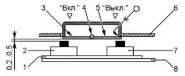
Next up is the power buttons. In order not to drill holes in the case of the multimeter, you can use the oval hole in it and the plastic button of the standard power switch 5 (Fig. 6). First, the button itself should be finalized: since it is hollow inside, it is necessary to cut out cover 1 from sheet polystyrene with a thickness of about 3 mm and make a recess in its middle part with a round file to a depth of about 0,5 ... 0,6 mm. Then, using a soldering iron, melt the steel axis 4 into the button (1 ... 1,5 in diameter and about 10 mm long), and then glue the cover 3. Dichloroethane is best used as glue. After the glue line hardens (this will happen in about a day), axis 4 should be carefully pulled out and the hole slightly drilled so that the newly inserted axis rotates freely, but without play. The modified button 5 with axis 4 is installed in the body of the multimeter, slightly fusing its ends into its upper wall 6. Additionally, they are fixed with narrow strips of the same polystyrene sheet glued with dichloroethane to the upper wall from the inside.
After waiting for the adhesive joints to completely harden and making sure that button 5 rotates freely in the oval hole of the upper wall of the multimeter case, the printed circuit board 1 with push-button switches 2 (SB1) and 7 (SB2) is put in place. This assembly is glued to the multimeter board 8 in such a way that when you press one of the sides, button 5 presses the stem of the SB1 push-button switch, and when you press the other, it presses the stem of the SB2 switch (of course, when the board is installed in the case). As glue, you can use the same varnish XB-784. It is possible that in order to reduce the stroke of button 5, necessary for the operation of switches SB1 and SB2, a gasket will have to be placed under board 1. Unnecessarily long rods of switches are shortened by melting with a soldering iron. A switch of this design can also be mounted in the M-830 multimeter. Since the conclusions 5-7 of the timer comparator were not used and there are only contact pads for them on the multimeter board, in their place is the pin part of the connector for connecting the converter. In place of output 8 of the comparator, the output "+8 V" of the converter is soldered, and in place of output 7 - its output "-8 V". The input for turning on the converter - the gate of the transistor VT2 - is soldered to the place of output 5, and "-G1" - to output 6 of the comparator. The terminals of the connector are connected to the corresponding circuits on the boards by wires in fluoroplastic insulation (Fig. 7).
Next, a battery, a connector for connecting a charger and a converter in the screen are fixed in the multimeter case. Literature
Author: E. Gerasimov
Machine for thinning flowers in gardens
02.05.2024 Advanced Infrared Microscope
02.05.2024 Air trap for insects
01.05.2024
▪ Ultra-precise tangled atomic clock ▪ Which language is the easiest
▪ section of the site Car. Article selection ▪ article What was to be proved. Popular expression ▪ article Why did the first transatlantic telegraph cable work for only a month? Detailed answer ▪ article CTO Administrator. Job description ▪ article Who touched the mirror? Focus secret. Focus Secret
Comments on the article: Eugene The scheme is successful, but when working from 1,5V, the field worker does not start. I changed the launch scheme. I moved the positive output of C2 beyond the switch of the M890G + multimeter and a plus appears on it after pressing the multimeter button. In order not to screw up the multimeter, I put a diode from the + power supply of the multimeter to the timer capacitor in the multimeter. Starting the converter made a short circuit with the drain-source button, which I installed under the multimeter button. Now the inclusion of the converter and the multimeter is carried out by the main button. Shutdown is also by pressing the multimeter button.
Home page | Library | Articles | Website map | Site Reviews
www.diagram.com.ua |


 Leave your comment on this article: